About me:
My name is Jia Nirmal. I am 14 years old and I go to the secondary school (MULO) in
the second grade.
I come from a family of 5: my parents, my older sister, my younger sister and
me. I love to innovate! I got my interest in innovating from my uncle and my aunt.
In my free time I work in my garden, fishing, riding a bike or making puzzles.
Sunday 13th of March 2022
Objective:
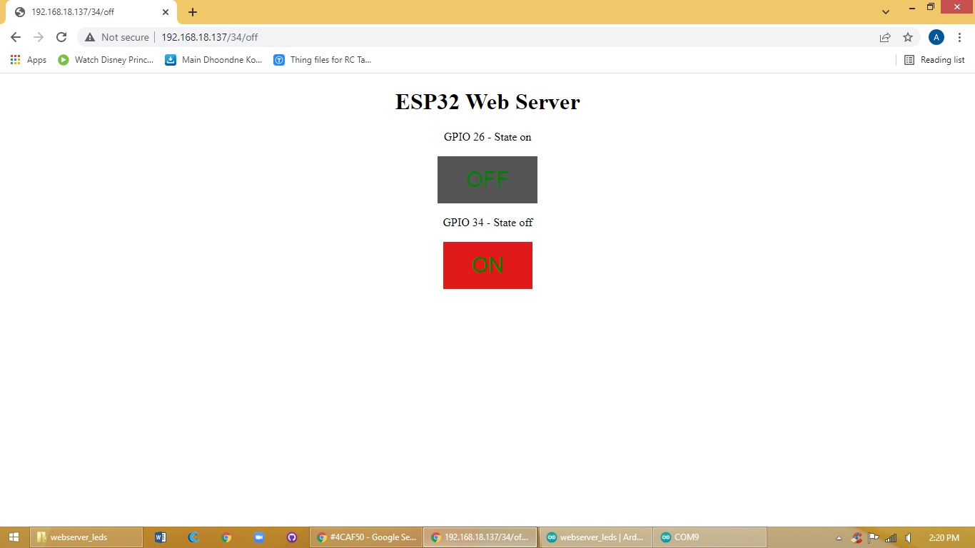
Today Miss Julie (Julie Sundar) was teaching me how to make a web server with the help of this page ESP32 Web Server using SPIFFS (SPI Flash File System) | Random Nerd Tutorials
Miss Julie explained the code to me and I understood it. After that i made the circuit and added the code in the ESP32-wrover. In the code you had to add your home network on which you are currently connected to. After that you go into the serial monitor. In the serial monitor you'll see a few dots in the beginning that means it's connecting to the wifi so you have to press the EN/RST button on your ESP32-wrover. After you press that button you'll get an IP address. After that you will have to copy and paste that address into google there you'll find two buttons which will control the two leds. When you turn on one led you will see above at the IP address a change saying pin 26 on.
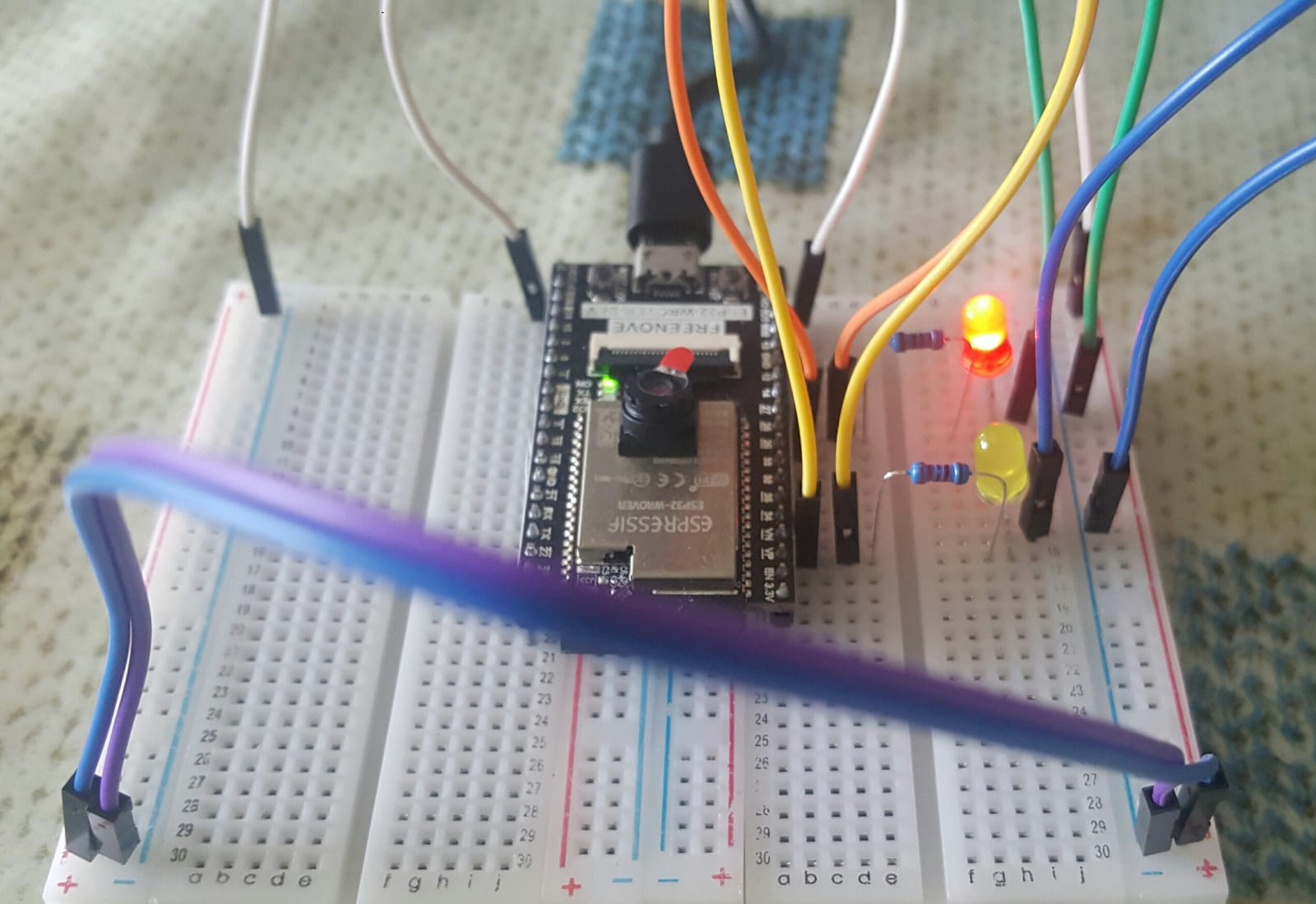
Component list:
Breadboard, ESP32-wrover, leds, resistors and jumpers.
Hands - On Screenshot
Code
/*********
Rui Santos
Complete project details at https://randomnerdtutorials.com
*********/
// Load Wi-Fi library
#include <WiFi.h>
// Replace with your network credentials
const char* ssid ="HUAWEI-2.4G-832N";
const char* password ="YuTyKpE4";
// Set web server port number to 80
WiFiServer server(80);
// Variable to store the HTTP request
String header;
// Auxiliary variables to store the current output state
String output26State = "off";
String output34State = "off";
// Assign output variables to GPIO pins
const int output26 = 27;
const int output34 = 34;
// Current time
unsigned long currentTime = millis();
// Previous time
unsigned long previousTime = 0;
// Define timeout time in milliseconds (example: 2000ms = 2s)
const long timeoutTime = 2000;
void setup() {
Serial.begin(115200);
// Initialize the output variables as outputs
pinMode(output26, OUTPUT);
pinMode(output34, OUTPUT);
// Set outputs to LOW
digitalWrite(output26, LOW);
digitalWrite(output34, LOW);
// Connect to Wi-Fi network with SSID and password
Serial.print("Connecting to ");
Serial.println(ssid);
WiFi.begin(ssid, password);
while (WiFi.status() != WL_CONNECTED) {
delay(500);
Serial.print(".");
}
// Print local IP address and start web server
Serial.println("");
Serial.println("WiFi connected.");
Serial.println("IP address: ");
Serial.println(WiFi.localIP());
server.begin();
}
void loop(){
WiFiClient client = server.available(); // Listen for incoming clients
if (client) { // If a new client connects,
currentTime = millis();
previousTime = currentTime;
Serial.println("New Client."); // print a message out in the serial port
String currentLine = ""; // make a String to hold incoming data from the client
while (client.connected() && currentTime - previousTime <= timeoutTime) { // loop while the client's connected
currentTime = millis();
if (client.available()) { // if there's bytes to read from the client,
char c = client.read(); // read a byte, then
Serial.write(c); // print it out the serial monitor
header += c;
if (c == '\n') { // if the byte is a newline character
// if the current line is blank, you got two newline characters in a row.
// that's the end of the client HTTP request, so send a response:
if (currentLine.length() == 0) {
// HTTP headers always start with a response code (e.g. HTTP/1.1 200 OK)
// and a content-type so the client knows what's coming, then a blank line:
client.println("HTTP/1.1 200 OK");
client.println("Content-type:text/html");
client.println("Connection: close");
client.println();
// turns the GPIOs on and off
if (header.indexOf("GET /26/on") >= 0) {
Serial.println("GPIO 26 on");
output26State = "on";
digitalWrite(output26, HIGH);
} else if (header.indexOf("GET /26/off") >= 0) {
Serial.println("GPIO 26 off");
output26State = "off";
digitalWrite(output26, LOW);
} else if (header.indexOf("GET /34/on") >= 0) {
Serial.println("GPIO 34 on");
output34State = "on";
digitalWrite(output34, HIGH);
} else if (header.indexOf("GET /34/off") >= 0) {
Serial.println("GPIO 34 off");
output34State = "off";
digitalWrite(output34, LOW);
}
// Display the HTML web page
client.println("<!DOCTYPE html><html>");
client.println("<head><meta name=\"viewport\" content=\"width=device-width, initial-scale=1\">");
client.println("<link rel=\"icon\" href=\"data:,\">");
// CSS to style the on/off buttons
// Feel free to change the background-color and font-size attributes to fit your preferences
client.println("<style>html { font-family: Helvetica; display: inline-block; margin: 0px auto; text-align: center;}");
client.println(".button { background-color: #4CAF50; border: none; color: white; padding: 16px 40px;");
client.println("text-decoration: none; font-size: 30px; margin: 2px; cursor: pointer;}");
client.println(".button2 {background-color: #555555;}</style></head>");
// Web Page Heading
client.println("<body><h1>ESP32 Web Server</h1>");
// Display current state, and ON/OFF buttons for GPIO 26
client.println("<p>GPIO 26 - State " + output26State + "</p>");
// If the output26State is off, it displays the ON button
if (output26State=="off") {
client.println("<p><a href=\"/26/on\"><button class=\"button\">ON</button></a></p>");
} else {
client.println("<p><a href=\"/26/off\"><button class=\"button button2\">OFF</button></a></p>");
}
// Display current state, and ON/OFF buttons for GPIO 27
client.println("<p>GPIO 34 - State " + output34State + "</p>");
// If the output34State is off, it displays the ON button
if (output34State=="off") {
client.println("<p><a href=\"/34/on\"><button class=\"button\">ON</button></a></p>");
} else {
client.println("<p><a href=\"/34/off\"><button class=\"button button2\">OFF</button></a></p>");
}
client.println("</body></html>");
// The HTTP response ends with another blank line
client.println();
// Break out of the while loop
break;
} else { // if you got a newline, then clear currentLine
currentLine = "";
}
} else if (c != '\r') { // if you got anything else but a carriage return character,
currentLine += c; // add it to the end of the currentLine
}
}
}
// Clear the header variable
header = "";
// Close the connection
client.stop();
Serial.println("Client disconnected.");
Serial.println("");
}
}
Mistakes:
Do not add space between “ =” and “HUAWEI-2.4G-832N". Or else wont work.
Tuesday 15th of March 2022
Objective
Today I learned how to get a “ESP32 cam” to work. The esp32-cam doesn't have a port on its own, so for uploading the code we need a FTDI programmer. With the help of that we get the code into the esp32-cam. After you upload the code you'll go to the serial monitor and get an IP address. When you go to that address you'll see a start button at the bottom.
Component list
Esp32-cam, FTDI programmer, usb cable and jumpers.
Hands - On Screenshot
Code
#include "esp_camera.h"
#include <WiFi.h>
//
// WARNING!!! PSRAM IC required for UXGA resolution and high JPEG quality
// Ensure ESP32 Wrover Module or other board with PSRAM is selected
// Partial images will be transmitted if image exceeds buffer size
//
// Select camera model
//#define CAMERA_MODEL_WROVER_KIT // Has PSRAM
//#define CAMERA_MODEL_ESP_EYE // Has PSRAM
//#define CAMERA_MODEL_M5STACK_PSRAM // Has PSRAM
//#define CAMERA_MODEL_M5STACK_V2_PSRAM // M5Camera version B Has PSRAM
//#define CAMERA_MODEL_M5STACK_WIDE // Has PSRAM
//#define CAMERA_MODEL_M5STACK_ESP32CAM // No PSRAM
//#define CAMERA_MODEL_M5STACK_UNITCAM // No PSRAM
#define CAMERA_MODEL_AI_THINKER // Has PSRAM
//#define CAMERA_MODEL_TTGO_T_JOURNAL // No PSRAM
#include "camera_pins.h"
const char* ssid ="HUAWEI-2.4G-832N";
const char* password ="YuTyKpE4";
void startCameraServer();
void setup() {
Serial.begin(115200);
Serial.setDebugOutput(true);
Serial.println();
camera_config_t config;
config.ledc_channel = LEDC_CHANNEL_0;
config.ledc_timer = LEDC_TIMER_0;
config.pin_d0 = Y2_GPIO_NUM;
config.pin_d1 = Y3_GPIO_NUM;
config.pin_d2 = Y4_GPIO_NUM;
config.pin_d3 = Y5_GPIO_NUM;
config.pin_d4 = Y6_GPIO_NUM;
config.pin_d5 = Y7_GPIO_NUM;
config.pin_d6 = Y8_GPIO_NUM;
config.pin_d7 = Y9_GPIO_NUM;
config.pin_xclk = XCLK_GPIO_NUM;
config.pin_pclk = PCLK_GPIO_NUM;
config.pin_vsync = VSYNC_GPIO_NUM;
config.pin_href = HREF_GPIO_NUM;
config.pin_sscb_sda = SIOD_GPIO_NUM;
config.pin_sscb_scl = SIOC_GPIO_NUM;
config.pin_pwdn = PWDN_GPIO_NUM;
config.pin_reset = RESET_GPIO_NUM;
config.xclk_freq_hz = 20000000;
config.pixel_format = PIXFORMAT_JPEG;
// if PSRAM IC present, init with UXGA resolution and higher JPEG quality
// for larger pre-allocated frame buffer.
if(psramFound()){
config.frame_size = FRAMESIZE_UXGA;
config.jpeg_quality = 10;
config.fb_count = 2;
} else {
config.frame_size = FRAMESIZE_SVGA;
config.jpeg_quality = 12;
config.fb_count = 1;
}
#if defined(CAMERA_MODEL_ESP_EYE)
pinMode(13, INPUT_PULLUP);
pinMode(14, INPUT_PULLUP);
#endif
// camera init
esp_err_t err = esp_camera_init(&config);
if (err != ESP_OK) {
Serial.printf("Camera init failed with error 0x%x", err);
return;
}
sensor_t * s = esp_camera_sensor_get();
// initial sensors are flipped vertically and colors are a bit saturated
if (s->id.PID == OV3660_PID) {
s->set_vflip(s, 1); // flip it back
s->set_brightness(s, 1); // up the brightness just a bit
s->set_saturation(s, -2); // lower the saturation
}
// drop down frame size for higher initial frame rate
s->set_framesize(s, FRAMESIZE_QVGA);
#if defined(CAMERA_MODEL_M5STACK_WIDE) || defined(CAMERA_MODEL_M5STACK_ESP32CAM)
s->set_vflip(s, 1);
s->set_hmirror(s, 1);
#endif
WiFi.begin(ssid, password);
while (WiFi.status() != WL_CONNECTED) {
delay(500);
Serial.print(".");
}
Serial.println("");
Serial.println("WiFi connected");
startCameraServer();
Serial.print("Camera Ready! Use 'http://");
Serial.print(WiFi.localIP());
Serial.println("' to connect");
}
void loop() {
// put your main code here, to run repeatedly:
delay(10000);
}
Mistakes
None.
Sunday 20th of March 2022
Objective
Today I had to upload the code from this link > https://randomnerdtutorials.com/esp32-cam-car-robot-web-server/ into my ESP32-CAM. But it wasn't going. Every time it said an error. So Miss Julie is gonna check why it isn't working.
Component list
ESP32-CAM, L298N motor driver, FTDI programmer, dc motors, battery pack and cables.
Code
/*********
Rui Santos
Complete instructions at https://RandomNerdTutorials.com/esp32-cam-projects-ebook/
Permission is hereby granted, free of charge, to any person obtaining a copy of this software and associated documentation files.
The above copyright notice and this permission notice shall be included in all copies or substantial portions of the Software.
*********/
#include "esp_camera.h"
#include <WiFi.h>
#include "esp_timer.h"
#include "img_converters.h"
#include "Arduino.h"
#include "fb_gfx.h"
#include "soc/soc.h" // disable brownout problems
#include "soc/rtc_cntl_reg.h" // disable brownout problems
#include "esp_http_server.h"
// Replace with your network credentials
const char* ssid ="HUWAWEI-2.4G-832N";
const char* password ="YuTyKpE4";
#define PART_BOUNDARY "123456789000000000000987654321"
#define CAMERA_MODEL_AI_THINKER
//#define CAMERA_MODEL_M5STACK_PSRAM
//#define CAMERA_MODEL_M5STACK_WITHOUT_PSRAM
//#define CAMERA_MODEL_M5STACK_PSRAM_B
//#define CAMERA_MODEL_WROVER_KIT
#if defined(CAMERA_MODEL_WROVER_KIT)
#define PWDN_GPIO_NUM -1
#define RESET_GPIO_NUM -1
#define XCLK_GPIO_NUM 21
#define SIOD_GPIO_NUM 26
#define SIOC_GPIO_NUM 27
#define Y9_GPIO_NUM 35
#define Y8_GPIO_NUM 34
#define Y7_GPIO_NUM 39
#define Y6_GPIO_NUM 36
#define Y5_GPIO_NUM 19
#define Y4_GPIO_NUM 18
#define Y3_GPIO_NUM 5
#define Y2_GPIO_NUM 4
#define VSYNC_GPIO_NUM 25
#define HREF_GPIO_NUM 23
#define PCLK_GPIO_NUM 22
#elif defined(CAMERA_MODEL_M5STACK_PSRAM)
#define PWDN_GPIO_NUM -1
#define RESET_GPIO_NUM 15
#define XCLK_GPIO_NUM 27
#define SIOD_GPIO_NUM 25
#define SIOC_GPIO_NUM 23
#define Y9_GPIO_NUM 19
#define Y8_GPIO_NUM 36
#define Y7_GPIO_NUM 18
#define Y6_GPIO_NUM 39
#define Y5_GPIO_NUM 5
#define Y4_GPIO_NUM 34
#define Y3_GPIO_NUM 35
#define Y2_GPIO_NUM 32
#define VSYNC_GPIO_NUM 22
#define HREF_GPIO_NUM 26
#define PCLK_GPIO_NUM 21
#elif defined(CAMERA_MODEL_M5STACK_WITHOUT_PSRAM)
#define PWDN_GPIO_NUM -1
#define RESET_GPIO_NUM 15
#define XCLK_GPIO_NUM 27
#define SIOD_GPIO_NUM 25
#define SIOC_GPIO_NUM 23
#define Y9_GPIO_NUM 19
#define Y8_GPIO_NUM 36
#define Y7_GPIO_NUM 18
#define Y6_GPIO_NUM 39
#define Y5_GPIO_NUM 5
#define Y4_GPIO_NUM 34
#define Y3_GPIO_NUM 35
#define Y2_GPIO_NUM 17
#define VSYNC_GPIO_NUM 22
#define HREF_GPIO_NUM 26
#define PCLK_GPIO_NUM 21
#elif defined(CAMERA_MODEL_AI_THINKER)
#define PWDN_GPIO_NUM 32
#define RESET_GPIO_NUM -1
#define XCLK_GPIO_NUM 0
#define SIOD_GPIO_NUM 26
#define SIOC_GPIO_NUM 27
#define Y9_GPIO_NUM 35
#define Y8_GPIO_NUM 34
#define Y7_GPIO_NUM 39
#define Y6_GPIO_NUM 36
#define Y5_GPIO_NUM 21
#define Y4_GPIO_NUM 19
#define Y3_GPIO_NUM 18
#define Y2_GPIO_NUM 5
#define VSYNC_GPIO_NUM 25
#define HREF_GPIO_NUM 23
#define PCLK_GPIO_NUM 22
#elif defined(CAMERA_MODEL_M5STACK_PSRAM_B)
#define PWDN_GPIO_NUM -1
#define RESET_GPIO_NUM 15
#define XCLK_GPIO_NUM 27
#define SIOD_GPIO_NUM 22
#define SIOC_GPIO_NUM 23
#define Y9_GPIO_NUM 19
#define Y8_GPIO_NUM 36
#define Y7_GPIO_NUM 18
#define Y6_GPIO_NUM 39
#define Y5_GPIO_NUM 5
#define Y4_GPIO_NUM 34
#define Y3_GPIO_NUM 35
#define Y2_GPIO_NUM 32
#define VSYNC_GPIO_NUM 25
#define HREF_GPIO_NUM 26
#define PCLK_GPIO_NUM 21
#else
#error "Camera model not selected"
#endif
#define MOTOR_1_PIN_1 14
#define MOTOR_1_PIN_2 15
#define MOTOR_2_PIN_1 13
#define MOTOR_2_PIN_2 12
static const char* _STREAM_CONTENT_TYPE = "multipart/x-mixed-replace;boundary=" PART_BOUNDARY;
static const char* _STREAM_BOUNDARY = "\r\n--" PART_BOUNDARY "\r\n";
static const char* _STREAM_PART = "Content-Type: image/jpeg\r\nContent-Length: %u\r\n\r\n";
httpd_handle_t camera_httpd = NULL;
httpd_handle_t stream_httpd = NULL;
static const char PROGMEM INDEX_HTML[] = R"rawliteral(
<html>
<head>
<title>ESP32-CAM Robot</title>
<meta name="viewport" content="width=device-width, initial-scale=1">
<style>
body { font-family: Arial; text-align: center; margin:0px auto; padding-top: 30px;}
table { margin-left: auto; margin-right: auto; }
td { padding: 8 px; }
.button {
background-color: #2f4468;
border: none;
color: white;
padding: 10px 20px;
text-align: center;
text-decoration: none;
display: inline-block;
font-size: 18px;
margin: 6px 3px;
cursor: pointer;
-webkit-touch-callout: none;
-webkit-user-select: none;
-khtml-user-select: none;
-moz-user-select: none;
-ms-user-select: none;
user-select: none;
-webkit-tap-highlight-color: rgba(0,0,0,0);
}
img { width: auto ;
max-width: 100% ;
height: auto ;
}
</style>
</head>
<body>
<h1>ESP32-CAM Robot</h1>
<img src="" id="photo" >
<table>
<tr><td colspan="3" align="center"><button class="button" onmousedown="toggleCheckbox('forward');" ontouchstart="toggleCheckbox('forward');" onmouseup="toggleCheckbox('stop');" ontouchend="toggleCheckbox('stop');">Forward</button></td></tr>
<tr><td align="center"><button class="button" onmousedown="toggleCheckbox('left');" ontouchstart="toggleCheckbox('left');" onmouseup="toggleCheckbox('stop');" ontouchend="toggleCheckbox('stop');">Left</button></td><td align="center"><button class="button" onmousedown="toggleCheckbox('stop');" ontouchstart="toggleCheckbox('stop');">Stop</button></td><td align="center"><button class="button" onmousedown="toggleCheckbox('right');" ontouchstart="toggleCheckbox('right');" onmouseup="toggleCheckbox('stop');" ontouchend="toggleCheckbox('stop');">Right</button></td></tr>
<tr><td colspan="3" align="center"><button class="button" onmousedown="toggleCheckbox('backward');" ontouchstart="toggleCheckbox('backward');" onmouseup="toggleCheckbox('stop');" ontouchend="toggleCheckbox('stop');">Backward</button></td></tr>
</table>
<script>
function toggleCheckbox(x) {
var xhr = new XMLHttpRequest();
xhr.open("GET", "/action?go=" + x, true);
xhr.send();
}
window.onload = document.getElementById("photo").src = window.location.href.slice(0, -1) + ":81/stream";
</script>
</body>
</html>
)rawliteral";
static esp_err_t index_handler(httpd_req_t *req){
httpd_resp_set_type(req, "text/html");
return httpd_resp_send(req, (const char *)INDEX_HTML, strlen(INDEX_HTML));
}
static esp_err_t stream_handler(httpd_req_t *req){
camera_fb_t * fb = NULL;
esp_err_t res = ESP_OK;
size_t _jpg_buf_len = 0;
uint8_t * _jpg_buf = NULL;
char * part_buf[64];
res = httpd_resp_set_type(req, _STREAM_CONTENT_TYPE);
if(res != ESP_OK){
return res;
}
while(true){
fb = esp_camera_fb_get();
if (!fb) {
Serial.println("Camera capture failed");
res = ESP_FAIL;
} else {
if(fb->width > 400){
if(fb->format != PIXFORMAT_JPEG){
bool jpeg_converted = frame2jpg(fb, 80, &_jpg_buf, &_jpg_buf_len);
esp_camera_fb_return(fb);
fb = NULL;
if(!jpeg_converted){
Serial.println("JPEG compression failed");
res = ESP_FAIL;
}
} else {
_jpg_buf_len = fb->len;
_jpg_buf = fb->buf;
}
}
}
if(res == ESP_OK){
size_t hlen = snprintf((char *)part_buf, 64, _STREAM_PART, _jpg_buf_len);
res = httpd_resp_send_chunk(req, (const char *)part_buf, hlen);
}
if(res == ESP_OK){
res = httpd_resp_send_chunk(req, (const char *)_jpg_buf, _jpg_buf_len);
}
if(res == ESP_OK){
res = httpd_resp_send_chunk(req, _STREAM_BOUNDARY, strlen(_STREAM_BOUNDARY));
}
if(fb){
esp_camera_fb_return(fb);
fb = NULL;
_jpg_buf = NULL;
} else if(_jpg_buf){
free(_jpg_buf);
_jpg_buf = NULL;
}
if(res != ESP_OK){
break;
}
//Serial.printf("MJPG: %uB\n",(uint32_t)(_jpg_buf_len));
}
return res;
}
static esp_err_t cmd_handler(httpd_req_t *req){
char* buf;
size_t buf_len;
char variable[32] = {0,};
buf_len = httpd_req_get_url_query_len(req) + 1;
if (buf_len > 1) {
buf = (char*)malloc(buf_len);
if(!buf){
httpd_resp_send_500(req);
return ESP_FAIL;
}
if (httpd_req_get_url_query_str(req, buf, buf_len) == ESP_OK) {
if (httpd_query_key_value(buf, "go", variable, sizeof(variable)) == ESP_OK) {
} else {
free(buf);
httpd_resp_send_404(req);
return ESP_FAIL;
}
} else {
free(buf);
httpd_resp_send_404(req);
return ESP_FAIL;
}
free(buf);
} else {
httpd_resp_send_404(req);
return ESP_FAIL;
}
sensor_t * s = esp_camera_sensor_get();
int res = 0;
if(!strcmp(variable, "forward")) {
Serial.println("Forward");
digitalWrite(MOTOR_1_PIN_1, 1);
digitalWrite(MOTOR_1_PIN_2, 0);
digitalWrite(MOTOR_2_PIN_1, 1);
digitalWrite(MOTOR_2_PIN_2, 0);
}
else if(!strcmp(variable, "left")) {
Serial.println("Left");
digitalWrite(MOTOR_1_PIN_1, 0);
digitalWrite(MOTOR_1_PIN_2, 1);
digitalWrite(MOTOR_2_PIN_1, 1);
digitalWrite(MOTOR_2_PIN_2, 0);
}
else if(!strcmp(variable, "right")) {
Serial.println("Right");
digitalWrite(MOTOR_1_PIN_1, 1);
digitalWrite(MOTOR_1_PIN_2, 0);
digitalWrite(MOTOR_2_PIN_1, 0);
digitalWrite(MOTOR_2_PIN_2, 1);
}
else if(!strcmp(variable, "backward")) {
Serial.println("Backward");
digitalWrite(MOTOR_1_PIN_1, 0);
digitalWrite(MOTOR_1_PIN_2, 1);
digitalWrite(MOTOR_2_PIN_1, 0);
digitalWrite(MOTOR_2_PIN_2, 1);
}
else if(!strcmp(variable, "stop")) {
Serial.println("Stop");
digitalWrite(MOTOR_1_PIN_1, 0);
digitalWrite(MOTOR_1_PIN_2, 0);
digitalWrite(MOTOR_2_PIN_1, 0);
digitalWrite(MOTOR_2_PIN_2, 0);
}
else {
res = -1;
}
if(res){
return httpd_resp_send_500(req);
}
httpd_resp_set_hdr(req, "Access-Control-Allow-Origin", "*");
return httpd_resp_send(req, NULL, 0);
}
void startCameraServer(){
httpd_config_t config = HTTPD_DEFAULT_CONFIG();
config.server_port = 80;
httpd_uri_t index_uri = {
.uri = "/",
.method = HTTP_GET,
.handler = index_handler,
.user_ctx = NULL
};
httpd_uri_t cmd_uri = {
.uri = "/action",
.method = HTTP_GET,
.handler = cmd_handler,
.user_ctx = NULL
};
httpd_uri_t stream_uri = {
.uri = "/stream",
.method = HTTP_GET,
.handler = stream_handler,
.user_ctx = NULL
};
if (httpd_start(&camera_httpd, &config) == ESP_OK) {
httpd_register_uri_handler(camera_httpd, &index_uri);
httpd_register_uri_handler(camera_httpd, &cmd_uri);
}
config.server_port += 1;
config.ctrl_port += 1;
if (httpd_start(&stream_httpd, &config) == ESP_OK) {
httpd_register_uri_handler(stream_httpd, &stream_uri);
}
}
void setup() {
WRITE_PERI_REG(RTC_CNTL_BROWN_OUT_REG, 0); //disable brownout detector
pinMode(MOTOR_1_PIN_1, OUTPUT);
pinMode(MOTOR_1_PIN_2, OUTPUT);
pinMode(MOTOR_2_PIN_1, OUTPUT);
pinMode(MOTOR_2_PIN_2, OUTPUT);
Serial.begin(115200);
Serial.setDebugOutput(false);
camera_config_t config;
config.ledc_channel = LEDC_CHANNEL_0;
config.ledc_timer = LEDC_TIMER_0;
config.pin_d0 = Y2_GPIO_NUM;
config.pin_d1 = Y3_GPIO_NUM;
config.pin_d2 = Y4_GPIO_NUM;
config.pin_d3 = Y5_GPIO_NUM;
config.pin_d4 = Y6_GPIO_NUM;
config.pin_d5 = Y7_GPIO_NUM;
config.pin_d6 = Y8_GPIO_NUM;
config.pin_d7 = Y9_GPIO_NUM;
config.pin_xclk = XCLK_GPIO_NUM;
config.pin_pclk = PCLK_GPIO_NUM;
config.pin_vsync = VSYNC_GPIO_NUM;
config.pin_href = HREF_GPIO_NUM;
config.pin_sscb_sda = SIOD_GPIO_NUM;
config.pin_sscb_scl = SIOC_GPIO_NUM;
config.pin_pwdn = PWDN_GPIO_NUM;
config.pin_reset = RESET_GPIO_NUM;
config.xclk_freq_hz = 20000000;
config.pixel_format = PIXFORMAT_JPEG;
if(psramFound()){
config.frame_size = FRAMESIZE_VGA;
config.jpeg_quality = 10;
config.fb_count = 2;
} else {
config.frame_size = FRAMESIZE_SVGA;
config.jpeg_quality = 12;
config.fb_count = 1;
}
// Camera init
esp_err_t err = esp_camera_init(&config);
if (err != ESP_OK) {
Serial.printf("Camera init failed with error 0x%x", err);
return;
}
// Wi-Fi connection
WiFi.begin(ssid, password);
while (WiFi.status() != WL_CONNECTED) {
delay(500);
Serial.print(".");
}
Serial.println("");
Serial.println("WiFi connected");
Serial.print("Camera Stream Ready! Go to: http://");
Serial.println(WiFi.localIP());
// Start streaming web server
startCameraServer();
}
void loop() {
}
Mistakes
None.
Saturday 19th April 2022
Objective
Today we figured out the error of esp32 cam. I added the GPI0 and ground cables on the wrong pins. When you're done uploading your code, you should remove one of the grounds. In the code from the page we don't have a control for the speed of the dc motors. The controlling of the motors is called pwm. And the direction is called inputs.
Monday 16th May 2022
Objective
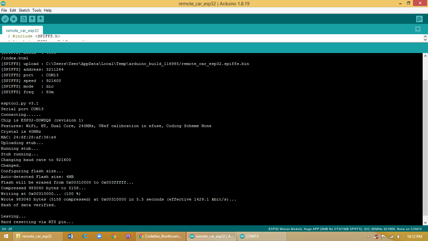
Today I had to upload the code with its data page. While uploading when it says 100%
then you need to remove the GPI0 from GND. After that you open the serial monitor up and press the reset button on the back.
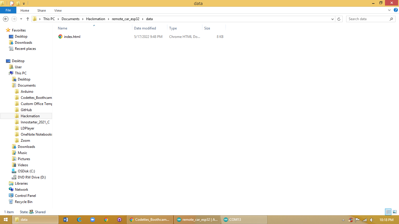
To get this code uploaded you need to have a good folder structure like this:
If the folder structure is not correct the code won't be able to upload.
While uploading if you get an error saying:
File not used: this pc/ documents/ arduino/ Libraries/ Wi-Fi.H
You need to go to your library and delete the Wi-Fi.h library. Then re-upload and it'll work!
After that we got to its page and connected the dc motors and tried them to work but they were not working. The page was crashing.
Component list
ESP32- CAM, FDI programmer, motor driver, dc motors and battery pack.
Code
/*
Rui Santos
Complete project details at https://RandomNerdTutorials.com/esp32-esp-now-wi-fi-web-server/
Permission is hereby granted, free of charge, to any person obtaining a copy
of this software and associated documentation files.
The above copyright notice and this permission notice shall be included in all
copies or substantial portions of the Software.
*/
#include <esp_now.h>
#include <WiFi.h>
#include <WiFiMulti.h>
#include "ESPAsyncWebServer.h"
#include <Arduino_JSON.h>
#include "esp_camera.h"
#include <WebSocketsServer.h>
#include "soc/soc.h" // disable brownout problems
#include "soc/rtc_cntl_reg.h" // disable brownout problems
#include "SPIFFS.h"
WiFiMulti wifiMulti;
// Robot
#include <ESP32Servo.h>
Servo myservo3;
Servo myservo1;
Servo myservo2;
Servo myservo4;
// Constants
const char *ssid2 = "HackWhack_J";
const char *password2 = "87654321";
const char *msg_toggle_led = "toggleLED";
const char *msg_get_led = "getLEDState";
const int dns_port = 53;
const int http_port = 80;
const int ws_port = 1337;
const int led_pin = 32;
const int armGround_pin = 27;
const int armDistance_pin = 15;
const int armHeight_pin = 14;
const int pin_speed1 = A0;
const int pin_motor1a = 21;
const int pin_motor1b = A5;
const int pin_motor2a = 13;
const int pin_motor2b = 33;
#define PWDN_GPIO_NUM 32
#define RESET_GPIO_NUM -1
#define XCLK_GPIO_NUM 0
#define SIOD_GPIO_NUM 26
#define SIOC_GPIO_NUM 27
#define Y9_GPIO_NUM 35
#define Y8_GPIO_NUM 34
#define Y7_GPIO_NUM 39
#define Y6_GPIO_NUM 36
#define Y5_GPIO_NUM 21
#define Y4_GPIO_NUM 19
#define Y3_GPIO_NUM 18
#define Y2_GPIO_NUM 5
#define VSYNC_GPIO_NUM 25
#define HREF_GPIO_NUM 23
#define PCLK_GPIO_NUM 22
WebSocketsServer webSocket = WebSocketsServer(81);
uint8_t cam_num;
bool connected = false;
// Structure example to receive data
// Must match the sender structure
typedef struct struct_message {
int id;
float temp;
float hum;
float soil;
float salt;
float light;
float batt;
unsigned int readingId;
} struct_message;
struct_message incomingReadings;
JSONVar board;
AsyncWebServer server(80);
AsyncEventSource events("/events");
char msg_buf[10];
int led_state = 120;
int arm_ground = 0;
// callback function that will be executed when data is received
void OnDataRecv(const uint8_t * mac_addr, const uint8_t *incomingData, int len) {
// Copies the sender mac address to a string
char macStr[18];
Serial.print("Packet received from: ");
snprintf(macStr, sizeof(macStr), "%02x:%02x:%02x:%02x:%02x:%02x",
mac_addr[0], mac_addr[1], mac_addr[2], mac_addr[3], mac_addr[4], mac_addr[5]);
Serial.println(macStr);
memcpy(&incomingReadings, incomingData, sizeof(incomingReadings));
board["id"] = incomingReadings.id;
board["temperature"] = incomingReadings.temp;
board["humidity"] = incomingReadings.hum;
board["soil"] = incomingReadings.soil;
board["salt"] = incomingReadings.salt;
board["light"] = incomingReadings.light;
board["batt"] = incomingReadings.batt;
board["readingId"] = String(incomingReadings.readingId);
String jsonString = JSON.stringify(board);
events.send(jsonString.c_str(), "new_readings", millis());
Serial.printf("Board ID %u: %u bytes\n", incomingReadings.id, len);
Serial.printf("t value: %4.2f \n", incomingReadings.temp);
Serial.printf("h value: %4.2f \n", incomingReadings.hum);
Serial.printf("s value: %4.2f \n", incomingReadings.soil);
Serial.printf("sa value: %4.2f \n", incomingReadings.salt);
Serial.printf("l value: %4.2f \n", incomingReadings.light);
Serial.printf("b value: %4.2f \n", incomingReadings.batt);
Serial.printf("readingID value: %d \n", incomingReadings.readingId);
Serial.println();
}
void configCamera(){
camera_config_t config;
config.ledc_channel = LEDC_CHANNEL_0;
config.ledc_timer = LEDC_TIMER_0;
config.pin_d0 = Y2_GPIO_NUM;
config.pin_d1 = Y3_GPIO_NUM;
config.pin_d2 = Y4_GPIO_NUM;
config.pin_d3 = Y5_GPIO_NUM;
config.pin_d4 = Y6_GPIO_NUM;
config.pin_d5 = Y7_GPIO_NUM;
config.pin_d6 = Y8_GPIO_NUM;
config.pin_d7 = Y9_GPIO_NUM;
config.pin_xclk = XCLK_GPIO_NUM;
config.pin_pclk = PCLK_GPIO_NUM;
config.pin_vsync = VSYNC_GPIO_NUM;
config.pin_href = HREF_GPIO_NUM;
config.pin_sscb_sda = SIOD_GPIO_NUM;
config.pin_sscb_scl = SIOC_GPIO_NUM;
config.pin_pwdn = PWDN_GPIO_NUM;
config.pin_reset = RESET_GPIO_NUM;
config.xclk_freq_hz = 20000000;
config.pixel_format = PIXFORMAT_JPEG;
config.frame_size = FRAMESIZE_QVGA;
config.jpeg_quality = 9;
config.fb_count = 1;
esp_err_t err = esp_camera_init(&config);
if (err != ESP_OK) {
Serial.printf("Camera init failed with error 0x%x", err);
return;
}
}
void liveCam(uint8_t num){
//capture a frame
camera_fb_t * fb = esp_camera_fb_get();
if (!fb) {
Serial.println("Frame buffer could not be acquired");
return;
}
//replace this with your own function
webSocket.sendBIN(num, fb->buf, fb->len);
//return the frame buffer back to be reused
esp_camera_fb_return(fb);
}
// Callback: receiving any WebSocket message
void onWebSocketEvent(uint8_t client_num,
WStype_t type,
uint8_t * payload,
size_t length) {
// Figure out the type of WebSocket event
switch(type) {
// Client has disconnected
case WStype_DISCONNECTED:
Serial.printf("[%u] Disconnected!\n", client_num);// Serial.printf("[%u] Disconnected!\n", num);
break;
// New client has connected
case WStype_CONNECTED:
{
cam_num = client_num;
connected = true;
IPAddress ip = webSocket.remoteIP(client_num);
Serial.printf("[%u] Connection from ", client_num);
Serial.println(ip.toString());
}
break;
// Handle text messages from client
case WStype_TEXT:
{
String string_payload = (char *)payload;
String motor_selector = string_payload.substring(0,4);
String motor_move_string = string_payload.substring(4);
int motor_move = motor_move_string.toInt();
Serial.println(motor_selector);
Serial.println(motor_move);
// Print out raw message
Serial.printf("[%u] Received text: %s\n", client_num, payload);
// Toggle LED
if ( motor_selector == "togg" ) {
led_state = (led_state==120) ? 180 : 120;
Serial.printf("Toggling LED to %u\n", led_state);
// Report the state of the LED
} else if (motor_selector == "gets" ) {
led_state = myservo1.read();
sprintf(msg_buf, "%d", led_state);
Serial.printf("Sending to [%u]: %s\n", client_num, msg_buf);
webSocket.sendTXT(client_num, msg_buf);
} else if (motor_selector == "turn") {
myservo1.write(motor_move);
} else if (motor_selector == "dist") {
myservo2.write(motor_move);
} else if (motor_selector == "heig") {
myservo4.write(motor_move);
} else if (motor_selector == "clam") {
myservo3.write(motor_move);
} else if (motor_selector == "gogo") {
motorMove("go");
delay(400);
motorMove("stop");
} else if (motor_selector == "back") {
motorMove("back");
delay(400);
motorMove("stop");
} else if (motor_selector == "left") {
motorMove("left");
delay(100);
motorMove("stop");
} else if (motor_selector == "righ") {
motorMove("right");
delay(100);
motorMove("stop");
} else {
Serial.println("[%u] Message not recognized");
}
break;
}
// For everything else: do nothing
case WStype_BIN:
case WStype_ERROR:
case WStype_FRAGMENT_TEXT_START:
case WStype_FRAGMENT_BIN_START:
case WStype_FRAGMENT:
case WStype_FRAGMENT_FIN:
default:
break;
}
}
// Callback: send homepage
void onIndexRequest(AsyncWebServerRequest *request) {
IPAddress remote_ip = request->client()->remoteIP();
Serial.println("[" + remote_ip.toString() +
"] HTTP GET request of " + request->url());
request->send(SPIFFS, "/index.html", "text/html");
}
// Callback: send style sheet
void onCSSRequest(AsyncWebServerRequest *request) {
IPAddress remote_ip = request->client()->remoteIP();
Serial.println("[" + remote_ip.toString() +
"] HTTP GET request of " + request->url());
request->send(SPIFFS, "/css/entireframework.min.css", "text/css");
}
// Callback: send style sheet
void onCSS2Request(AsyncWebServerRequest *request) {
IPAddress remote_ip = request->client()->remoteIP();
Serial.println("[" + remote_ip.toString() +
"] HTTP GET request of " + request->url());
request->send(SPIFFS, "/css/custom.css", "text/css");
}
// Callback: send style sheet
void onCSS3Request(AsyncWebServerRequest *request) {
IPAddress remote_ip = request->client()->remoteIP();
Serial.println("[" + remote_ip.toString() +
"] HTTP GET request of " + request->url());
request->send(SPIFFS, "/css/all.css", "text/css");
}
void onJSRequest(AsyncWebServerRequest *request) {
IPAddress remote_ip = request->client()->remoteIP();
Serial.println("[" + remote_ip.toString() +
"] HTTP GET request of " + request->url());
request->send(SPIFFS, "/css/entireframework.min.css", "text/css");
}
void onJS2Request(AsyncWebServerRequest *request) {
IPAddress remote_ip = request->client()->remoteIP();
Serial.println("[" + remote_ip.toString() +
"] HTTP GET request of " + request->url());
request->send(SPIFFS, "/js/jquery-1.9.1.min.js", "text/css");
}
// Callback: send 404 if requested file does not exist
void onPageNotFound(AsyncWebServerRequest *request) {
IPAddress remote_ip = request->client()->remoteIP();
Serial.println("[" + remote_ip.toString() +
"] HTTP GET request of " + request->url());
request->send(404, "text/plain", "Not found");
}
void setup() {
myservo3.attach(led_pin);
myservo1.attach(armGround_pin);
myservo2.attach(armDistance_pin);
myservo4.attach(armHeight_pin);
pinMode(pin_speed1,OUTPUT);
pinMode(pin_motor1a,OUTPUT);
pinMode(pin_motor1b,OUTPUT);
pinMode(pin_motor2a,OUTPUT);
pinMode(pin_motor2b,OUTPUT);
// Init LED and turn off
pinMode(led_pin, OUTPUT);
digitalWrite(led_pin, LOW);
// Initialize Serial Monitor
Serial.begin(115200);
// Start access point
WiFi.softAP(ssid2, password2);
// Print our IP address
Serial.println();
Serial.println("AP running");
Serial.print("My IP address: ");
Serial.println(WiFi.softAPIP());
wifiMulti.addAP("Team09", "H@ckTe@m)(");
wifiMulti.addAP("Virus", "RedEyeJedi44");
wifiMulti.addAP("ssid_from_AP_3", "your_password_for_AP_3");
Serial.println("Connecting Wifi...");
if(wifiMulti.run() == WL_CONNECTED) {
Serial.println("");
Serial.println("WiFi connected");
Serial.println("IP address: ");
Serial.println(WiFi.localIP());
}
if(wifiMulti.run() != WL_CONNECTED) {
Serial.println("WiFi not connected!");
delay(1000);
}
// Init ESP-NOW
if (esp_now_init() != ESP_OK) {
Serial.println("Error initializing ESP-NOW");
return;
}
// Once ESPNow is successfully Init, we will register for recv CB to
// get recv packer info
esp_now_register_recv_cb(OnDataRecv);
// Initialize SPIFFS
if (!SPIFFS.begin(true))
{
Serial.println("An Error has occurred while mounting SPIFFS");
return;
}
// On HTTP request for root, provide index.html file
server.on("/", HTTP_GET, onIndexRequest);
// On HTTP request for style sheet, provide style.css
server.on("/css/entireframework.min.css", HTTP_GET, onCSSRequest);
// On HTTP request for style sheet, provide style.css
server.on("/css/custom.css", HTTP_GET, onCSS2Request);
// On HTTP request for style sheet, provide style.css
server.on("/css/all.css", HTTP_GET, onCSS3Request);
// On HTTP request for style sheet, provide style.css
server.on("/js/custom.js", HTTP_GET, onJSRequest);
// On HTTP request for style sheet, provide style.css
server.on("/js/jquery-1.9.1.min.js", HTTP_GET, onJS2Request);
// Handle requests for pages that do not exist
server.onNotFound(onPageNotFound);
events.onConnect([](AsyncEventSourceClient *client){
if(client->lastId()){
Serial.printf("Client reconnected! Last message ID that it got is: %u\n", client->lastId());
}
// send event with message "hello!", id current millis
// and set reconnect delay to 1 second
client->send("hello!", NULL, millis(), 10000);
});
server.addHandler(&events);
server.begin();
webSocket.begin();
webSocket.onEvent(onWebSocketEvent);
configCamera();
}
void loop() {
//http_resp();
webSocket.loop();
if(connected == true){
liveCam(cam_num);
}
static unsigned long lastEventTime = millis();
static const unsigned long EVENT_INTERVAL_MS = 5000;
if ((millis() - lastEventTime) > EVENT_INTERVAL_MS) {
events.send("ping",NULL,millis());
lastEventTime = millis();
}
}
void motorMove(String move) {
if (move.equals("go"))
{
digitalWrite(pin_speed1,HIGH);
digitalWrite(pin_motor1a,HIGH);
digitalWrite(pin_motor1b,LOW);
digitalWrite(pin_motor2a,HIGH);
digitalWrite(pin_motor2b,LOW);
}
else if (move.equals("back"))
{
digitalWrite(pin_speed1,HIGH);
digitalWrite(pin_motor1a,LOW);
digitalWrite(pin_motor1b,HIGH);
digitalWrite(pin_motor2a,LOW);
digitalWrite(pin_motor2b,HIGH);
}
else if (move.equals("left"))
{
digitalWrite(pin_speed1,HIGH);
digitalWrite(pin_motor1a,LOW);
digitalWrite(pin_motor1b,HIGH);
digitalWrite(pin_motor2a,HIGH);
digitalWrite(pin_motor2b,LOW);
}
else if (move.equals("right"))
{
digitalWrite(pin_speed1,HIGH);
digitalWrite(pin_motor1a,HIGH);
digitalWrite(pin_motor1b,LOW);
digitalWrite(pin_motor2a,LOW);
digitalWrite(pin_motor2b,HIGH);
}
else if (move.equals("stop"))
{
digitalWrite(pin_speed1,LOW);
}
else
{
// nothing
}
}
Mistakes
Friday 20th of May 2022
Objective
Today we made the last parts of our rover. The dc’s and the servo and the cutter. The cutter is working with a dc motor. And the bedmaker works with a servo. Coded them both and still isn't working.
Code
#include <Servo.h>
Servo servo;
volatile int radarArray[2];
//serial
int state;
int flag = 0;
//motor basic
int motorlenA = 3;
int motorlin1 = 2;
int motorlin2 = 4;
int motorlenB = 11;
int motorlin3 = 12;
int motorlin4 = 13;
//motor Grass
int motor3enB = 9;
int motor3in3 = 7;
int motor3in4 = 8;
void setup()
{
Serial.begin(9600);
//servo.write(90);
servo.attach(5);
pinMode(motorlenA,OUTPUT);
pinMode(motorlin1,OUTPUT);
pinMode(motorlin2,OUTPUT);
pinMode(motorlenB,OUTPUT);
pinMode(motorlin3,OUTPUT);
pinMode(motorlin4,OUTPUT);
//speed
analogWrite(motorlenA,255);
analogWrite(motorlenB,255);
}
void sweepright()
{
servo.write(0); //right
delay(700);
radarArray[0];
}
void sweepleft()
{
servo.write(180); //left
delay(1200);
radarArray[1];
}
void forward()
{
digitalWrite(motorlin1,HIGH);//backwards
digitalWrite(motorlin2,LOW);
digitalWrite(motorlin3,HIGH);
digitalWrite(motorlin4,LOW);
//Serial.println("Foward");
}
void backwards(){
//motor
digitalWrite(motorlin1,LOW);//backwards
digitalWrite(motorlin2,HIGH);
digitalWrite(motorlin3,LOW);
digitalWrite(motorlin4,HIGH);
}
void left(){
digitalWrite(motorlin1,HIGH);
digitalWrite(motorlin2,LOW);
digitalWrite(motorlin3,LOW);
digitalWrite(motorlin4,LOW);
// Serial.println("left");
}
void right(){
digitalWrite(motorlin1,LOW);
digitalWrite(motorlin2,LOW);
digitalWrite(motorlin3,HIGH);
digitalWrite(motorlin4,LOW);
//Serial.println("right");
}
void stopm(){
//stop everything
digitalWrite(motorlin1,LOW);
digitalWrite(motorlin2,LOW);
digitalWrite(motorlin3,LOW);
digitalWrite(motorlin4,LOW);
//delay(1000);
}
void loop ()
{
sweepright();
delay (4000);
sweepleft();
delay (4000);
//Start serial
if (Serial.available() > 0 )
{
state = Serial.read();
flag = 0;
}
//serial
if(state == 'F')
{
if(flag == 0)
{
Serial.println("Go Forward");
forward();
flag = 1;
}
}
else if(state == 'B')
{
if(flag == 0)
{
Serial.println("Go Backwards");
backwards();
flag = 1;
}
}
else if(state == 'L')
{
if(flag == 0)
{
Serial.println("Go Left");
left();
flag = 1;
}
}
else if(state == 'R')
{
if(flag == 0)
{
Serial.println("Go Right");
right();
flag = 1;
}
}
else if(state == 'S')
{
if(flag == 0)
{
Serial.println("stop");
stopm();
flag = 1;
}
}
}
Friday 10th of June 2022
Objective
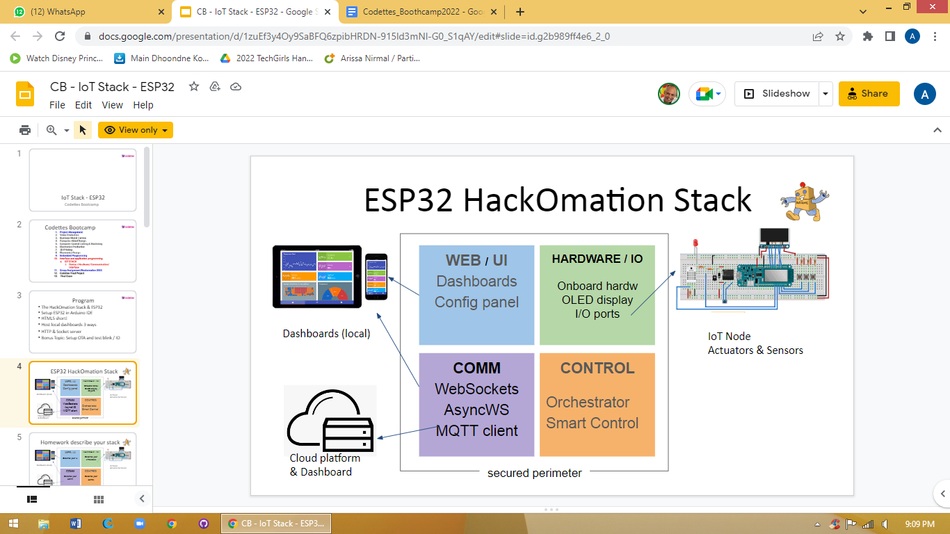
Today we got homework:
I need to make this. With the information of the hackomation.
Note: do it yourself!
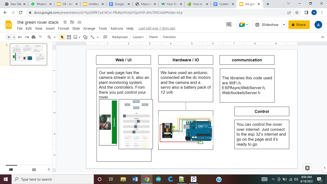
And this is how mine looks like:
Friday 17th of June
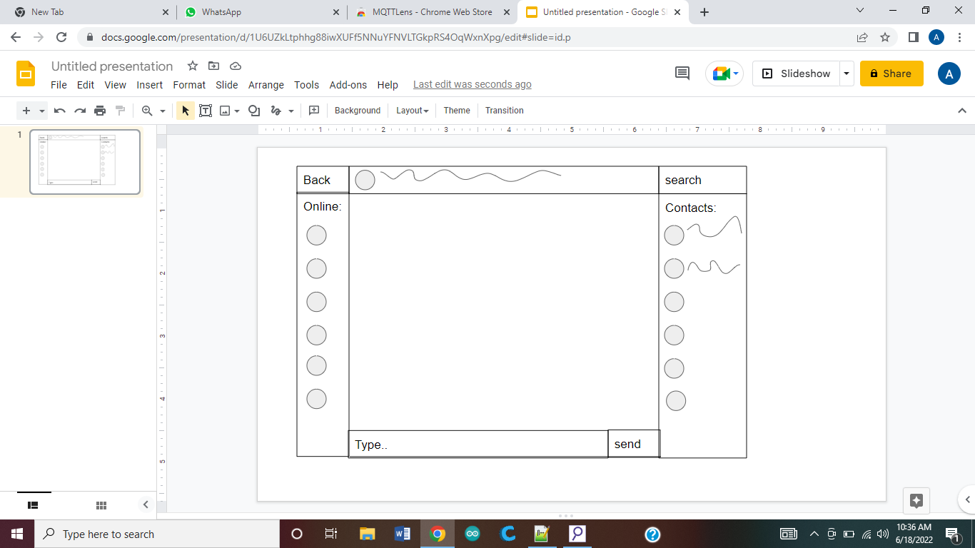
Objective:
Today we had to make our own chat app with a new design, maybe new features. First we had to sketch our ideas and here is mine:
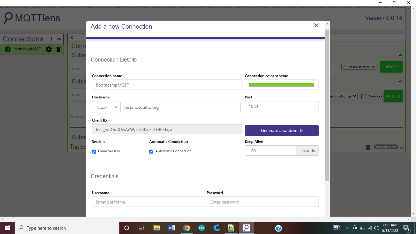
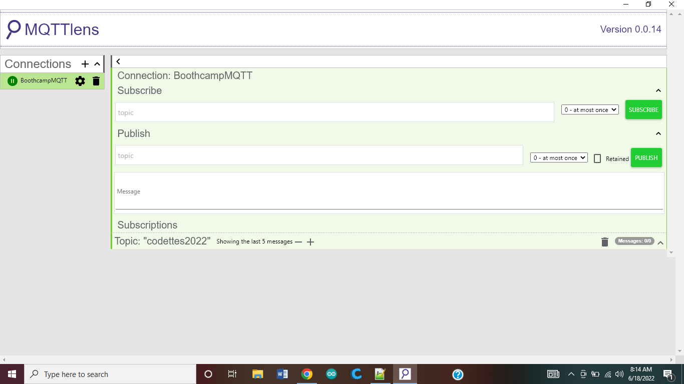
First we had to add MQTT lens to our chromes and made a quick chat group in there, now keep in mind before you subscribe have:
this. Don't forget to mark the “automatic connection”. After that you should get something like this:
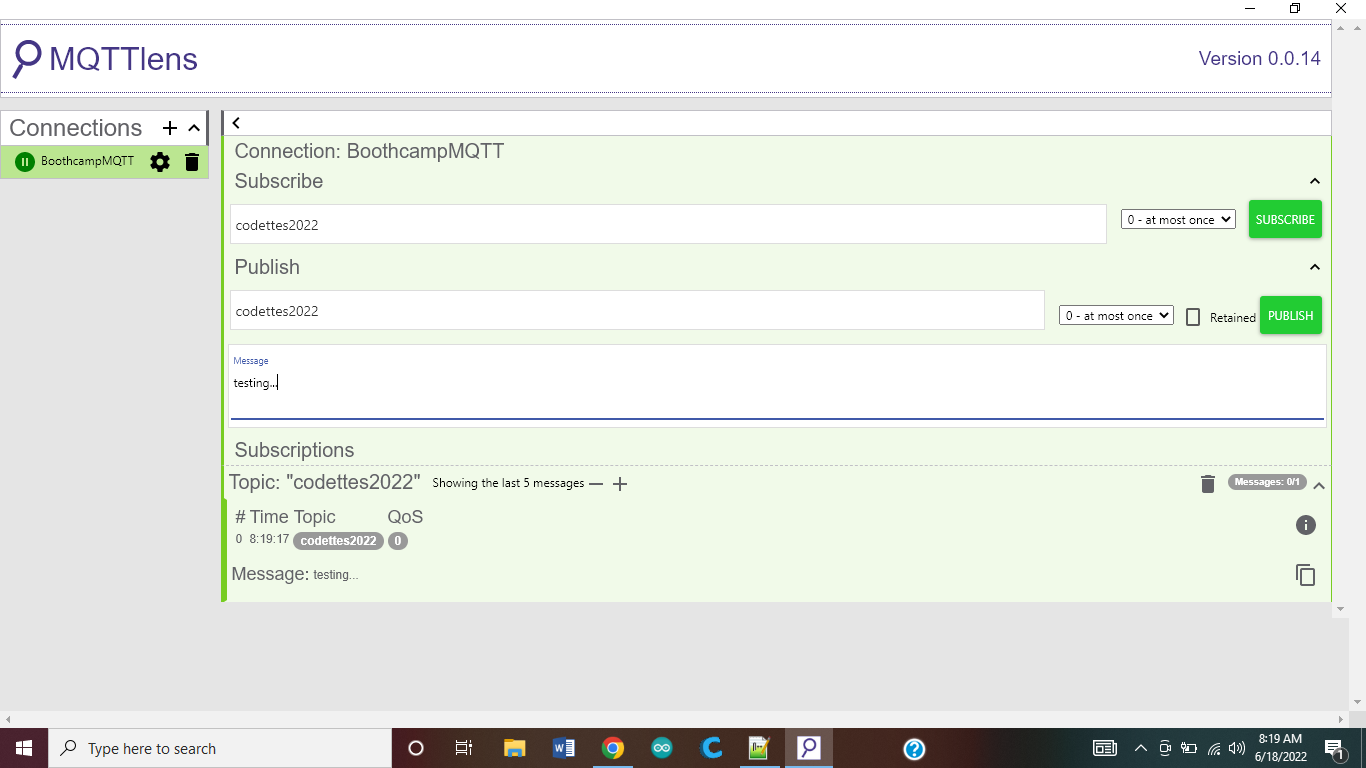
In here you will add your topic and then where do you want to publish your message that should be also the name of your topic. But before you can send a message in the group you need to subscribe to that group. That means if you've subscribed to it you'll get notifications from it. Anyone who sends a message there, you will be able to see it.
Like this:
So this is the first thing we did.
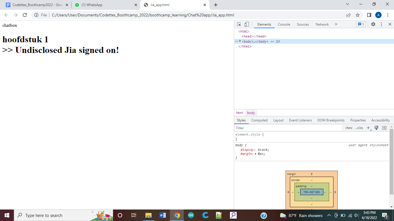
Now we code the html page we sketched in notepad++. What we did is just basic so it won't look that neat.
Saturday 18th of june 2022
Objective
Today we got over the basic html again and tried to make it. This is what I got
Now I just need style and add everything to it like I made in the MockUp.
Components
Notepad++, google and HTML Tutorial
Code
<html>
<header>
<script src="https://cdnjs.cloudflare.com/ajax/libs/paho-mqtt/1.0.1/mqttws31.js" type="text/javascript"></script>
</header>
<body>
<div id="chatbox">
<div>chatbox</div>
<div></div>
</div>
<h1 id="chatlog"> hoofdstuk 1 </h1>
<script>
// Create a client instance
client = new Paho.MQTT.Client("test.mosquitto.org", 8080, client_id="", clean_session="true", userdata="none", protocol="MQTTv311", transport="tcp");
// set callback handlers
client.onConnectionLost = onConnectionLost;
client.onMessageArrived = onMessageArrived;
// connect the client
client.connect({onSuccess:onConnect});
// called when the client connects
function onConnect() {
// Once a connection has been made, make a subscription and send a message.
console.log("onConnect");
client.subscribe("codettes2022");
message = new Paho.MQTT.Message("Undisclosed Jia signed on!");
message.destinationName = "codettes2022";
client.send(message);
}
function sendMessageButton(msgtext){
if (msgtext!=''){
message = new Paho.MQTT.Message("Alien says: " + msgtext);
message.destinationName = "codettes2022";
client.send(message);
}
}
// OR listen to the Enter event on n input box
function sendMsg(ele) {
if(event.key === 'Enter') {
message = new Paho.MQTT.Message("Alien says: " + ele.value);
message.destinationName = "codettes2022";
client.send(message);
//alert(ele.value);
ele.value = ""; // reset the input after entering
}
}
// called when the client loses its connection
function onConnectionLost(responseObject) {
if (responseObject.errorCode !== 0) {
console.log("onConnectionLost:"+responseObject.errorMessage);
}
}
// called when a message arrives
function onMessageArrived(message) {
console.log("onMessageArrived:"+ message.payloadString);
// To do: if user is myself do different style or ignore the message and write directly to log
document.getElementById("chatlog").innerHTML += "<br> >> " + message.payloadString
}
</script>
</body>
</html>
Friday 5th of August 2022
Objective
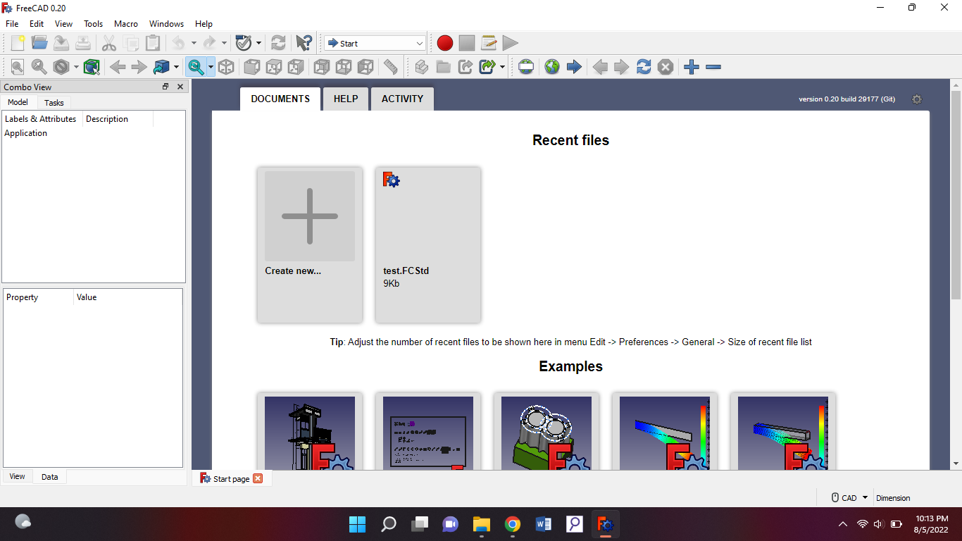
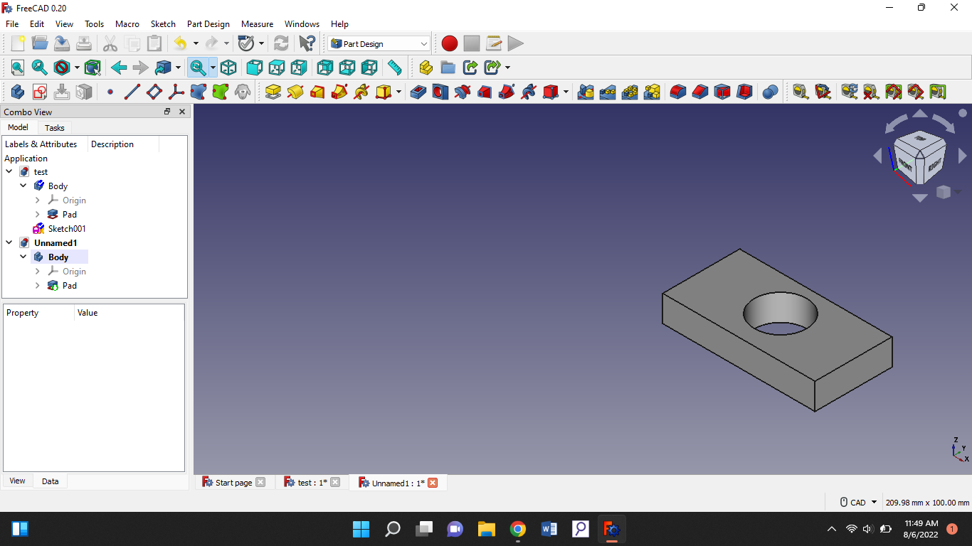
Today I joined the bootcamp again because for three weeks I was in America for the TechGirls program. So today we had to install freeCAD. So freeCAD is basically an app where you can design 3d and 2d designs.after download follow these instructions:
When you open it after installation you’ll get this:
Then you go to your workbench and put it on start. Workbench:
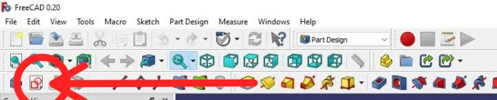
Then go to create new. You will be led to a new page. Then you go to your workbench again and change it to “part design”. There you will get new editing options. After that you go on the top and press create “sketch”. Here:
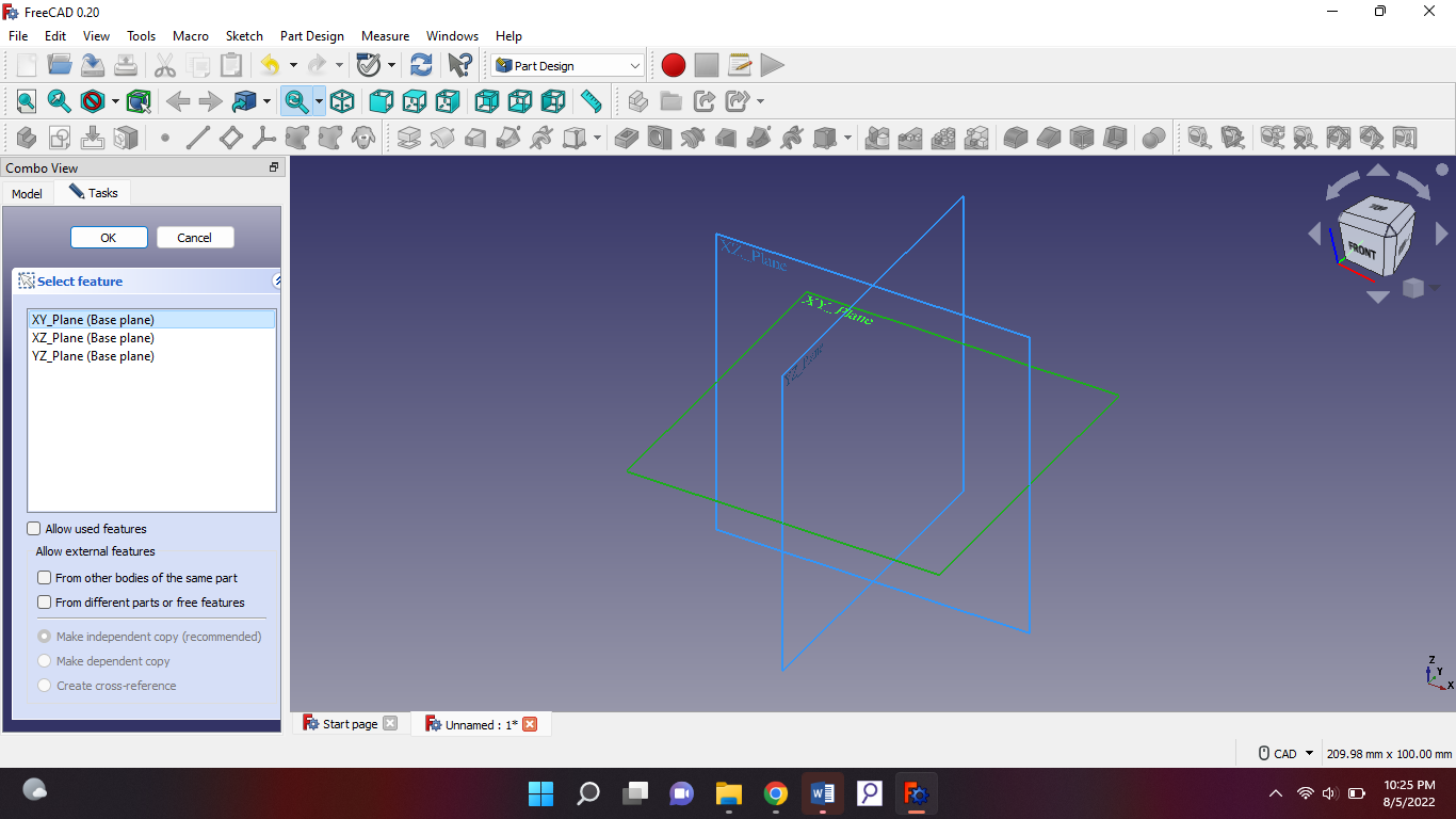
When you press that, you will get a few options on the side:
you should take the XY plane.
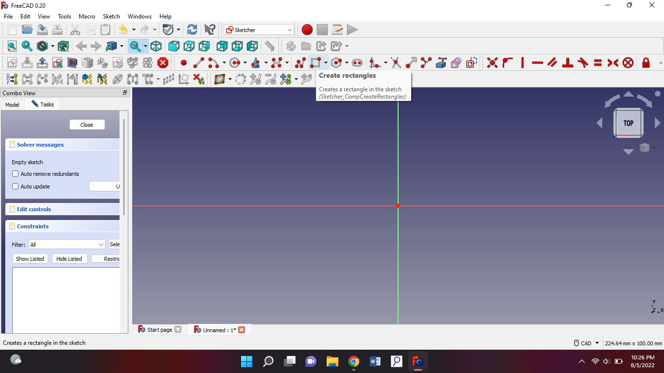
Then you create a rectangle with this tool:
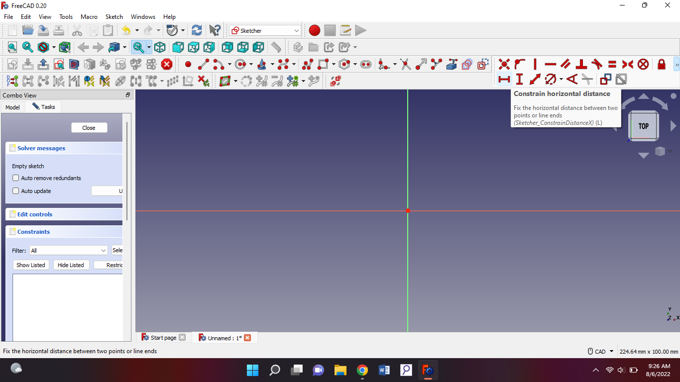
You take that and create your rectangle. Then you should make the horizontal side and vertical side to 100.00mm. With this:
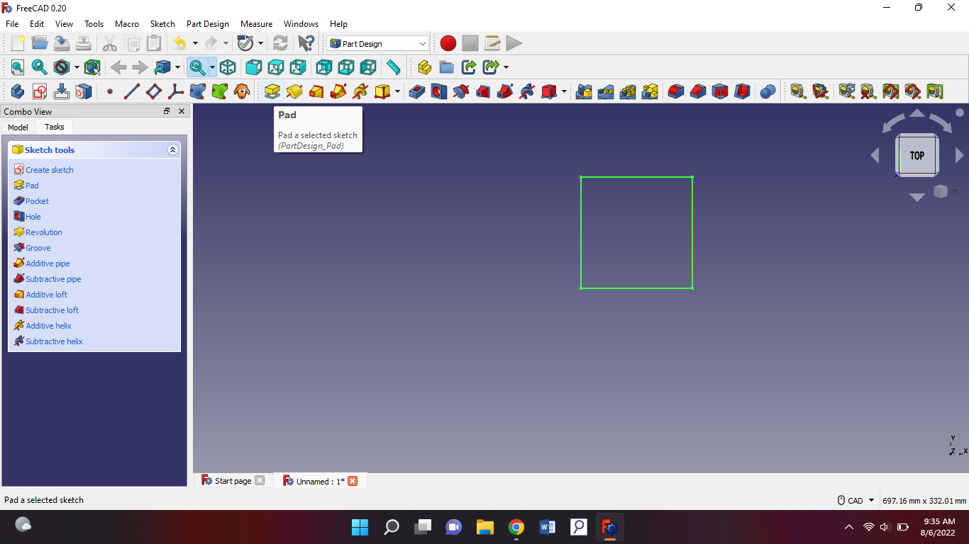
After that you press close on the task bar on the side. You will get new options and you need to press this one:
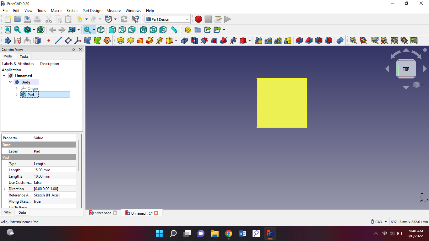
When you have pressed that you will see that your shape has changed its color. You will see on the side in tasks a highlighted mm’s. You have to put that to 15. After that you go to “model” on the side and pad has to be selected:
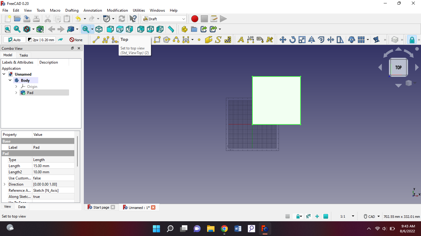
Then we're gonna export it but, when you export your workbench has to be on draft. When you have that, put you object on top view:
Now we're gonna export. Make sure: 1. Workbench has to be on draft 2. Pad has to be selected 3. The object has to be on top view.
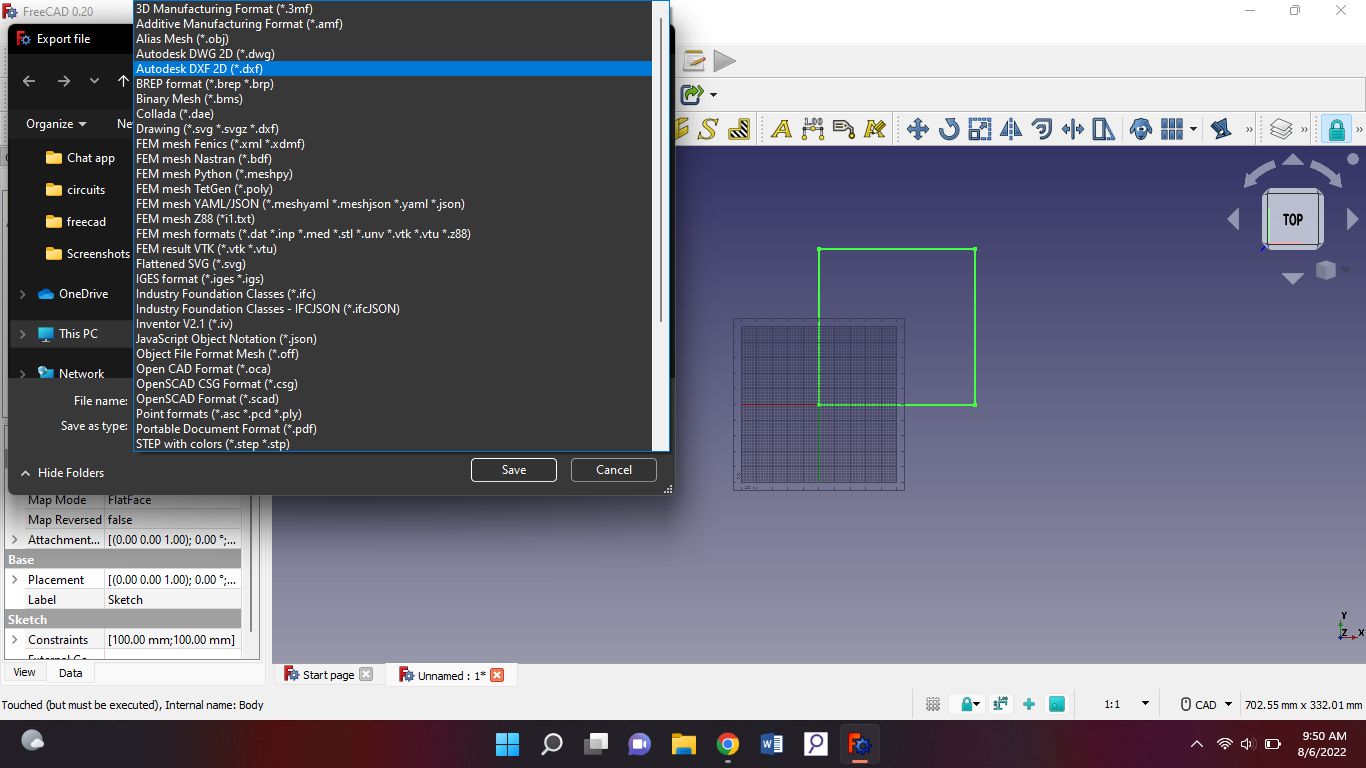
After checking all that, go to files select “export” then you'll be led to save the file. The file type has to be DXF:
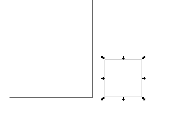
After it has been saved, open inkscape. Import the file into inkscape then you should be able to see this small box on the side:
If you see this, good. Now let's go back to freeCAD. And export the same file into stl type. Then import it in tinkercad.
Mistakes
None. Homework is to make a hole into the box. And I already did it:
Saturday 6th of August 2022
Objective
So today I had to brainstorm what my final project is gonna be. My final project will be DelMare. So DelMare is a kind of pump that will automatically spray water to plants on a big scale. But this already exists you might ask. I'm making this because it hasn't been introduced where I live yet. Now I have to make my business model canvas for this project.
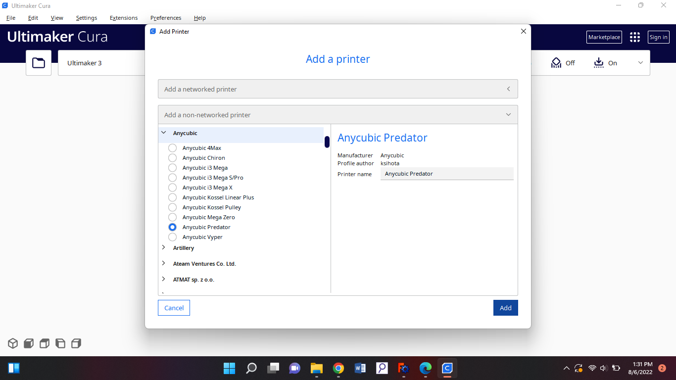
And today we also learned how to make a 3d object to print. So first of all we download and install the latest version of Cura. When you go to install cura you will get to add a printer and this is the kind of printer we have in the lab:
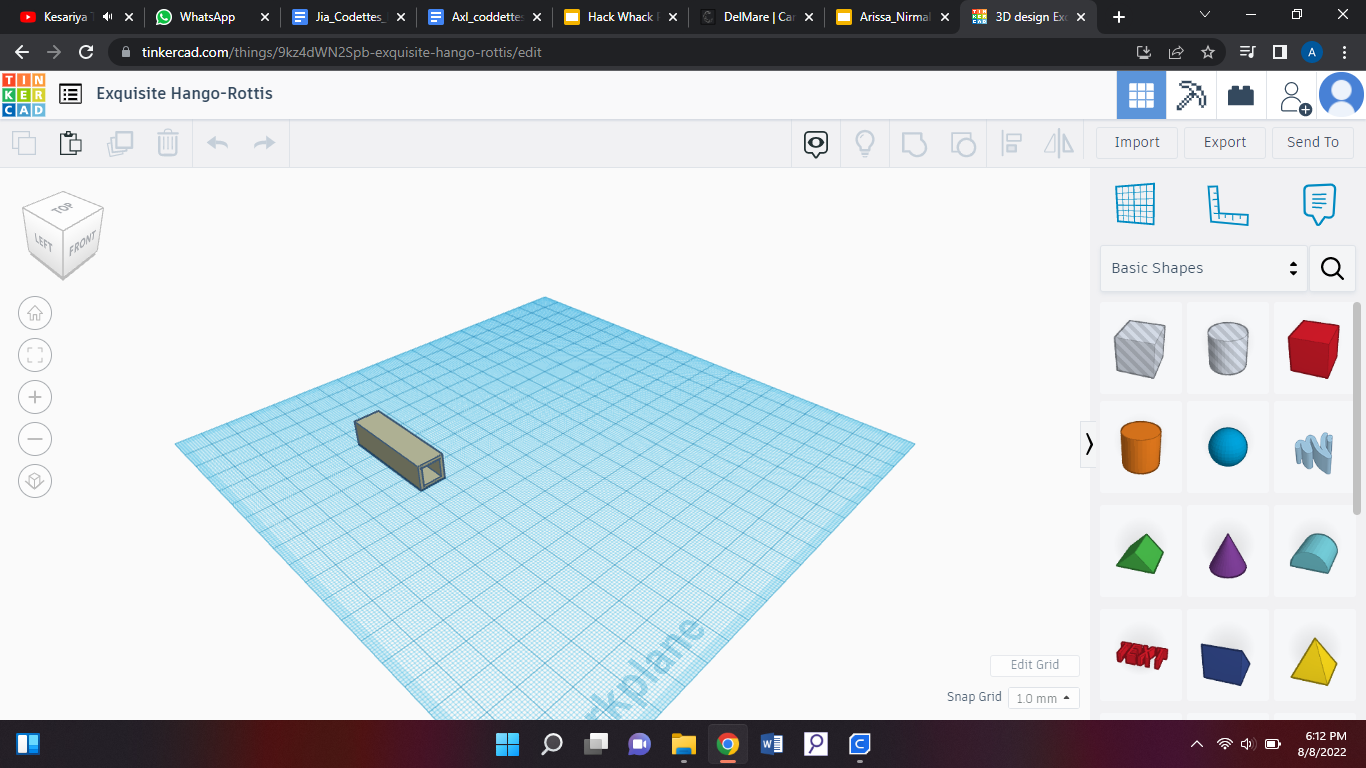
So we select that and then we are settled. I went to Tinkercad to design something, mine had to be under 15 minutes so I had to do something very small. So i designed this:
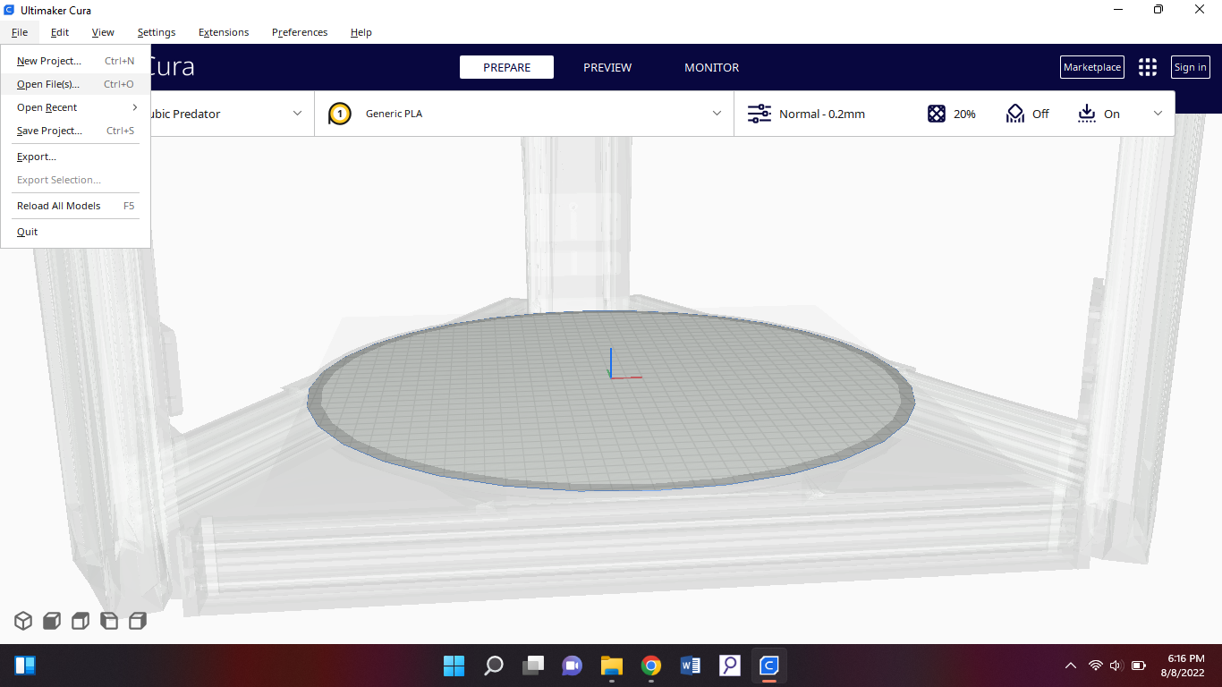
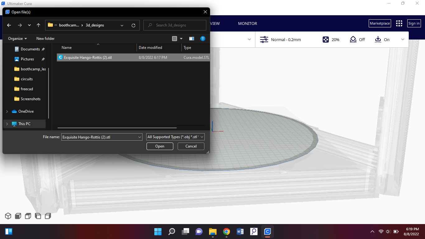
When you're done you need to export your design in a stl file. Then you open cura and go to file > open file(s)
You'll be led to your files, select the downloaded file from tinkercad.
Select your file and be sure that your type of plastic is PLA. When you've added your design into cura, on the side you will get the average time it takes to print. Then you save to disk, which has to be a G code file.
Business Model Canvas
Now that I have my final project, I have to start making my business model canvas. So what is a business model canvas? A business model canvas is used to introduce a new project that is released/ going to be released. In a business model canvas you have many subjects to explain
your project. For example:
value proposition, to fill this subject in you can ask the question “why should people buy my product?”. It's basically like, what is the core value that I deliver to my customers with my product?
Key partners: these are the partners that help you throughout making the project in a financial way.
Key resources: these are the most important things your project needs to be finished. Ex.: money.
Customer relationships: so basically you should make a relationship with your customer in which both of you have benefits, with the help of your product.
Channels: with channels it's meant, how will you introduce your product? Ex.: advertisement.
Customer segments: your target audience.
Cost structure:
Revenue streams:
Key activities: These are the activities you have to do to get your value proposition.
Saturday 13th of August 2022
Objective
Today we had to do 3 things. 1. Make a hole with freecad 2. Make a pocket in freecad 3. 3D print something.
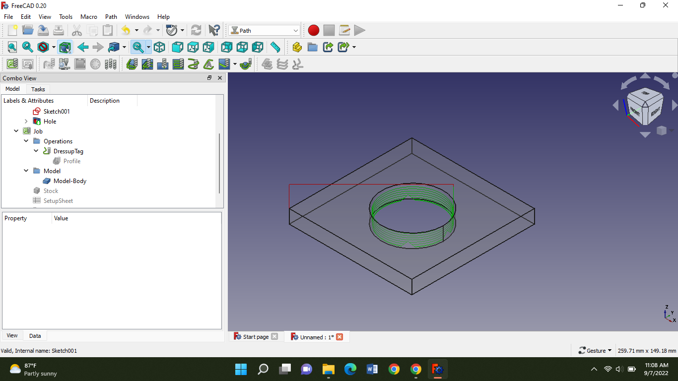
1 making a hole in freecad:
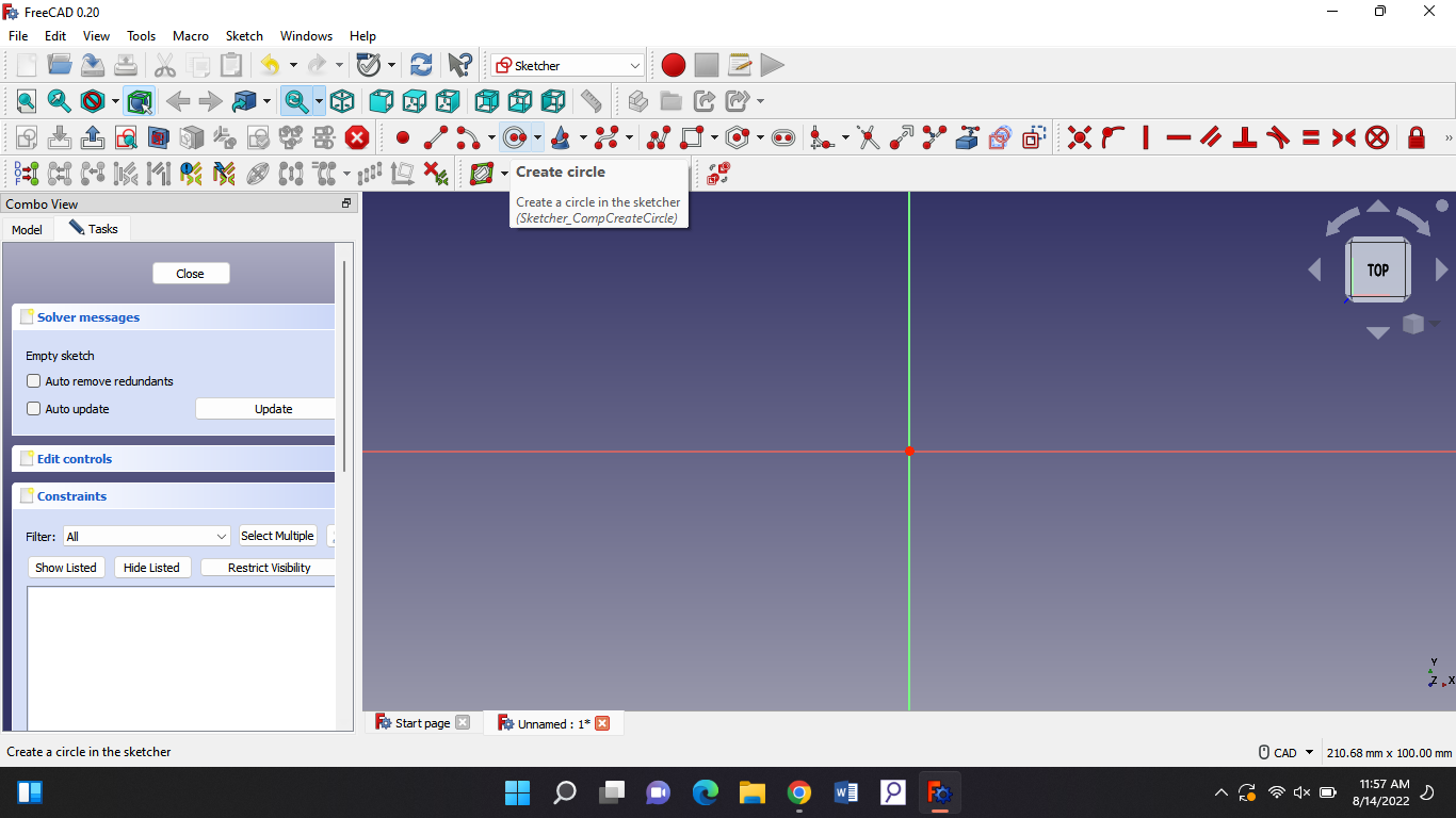
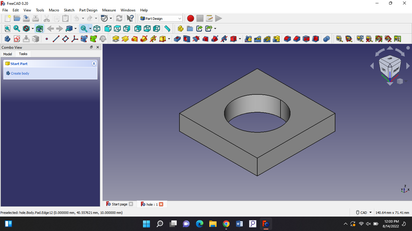
So the first what you have to do is go to freecad and make a square then put a circle in it with this feature:
Then you close the task bar on the side. You will get new features and then press the pad. You should see this:
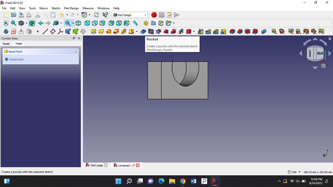
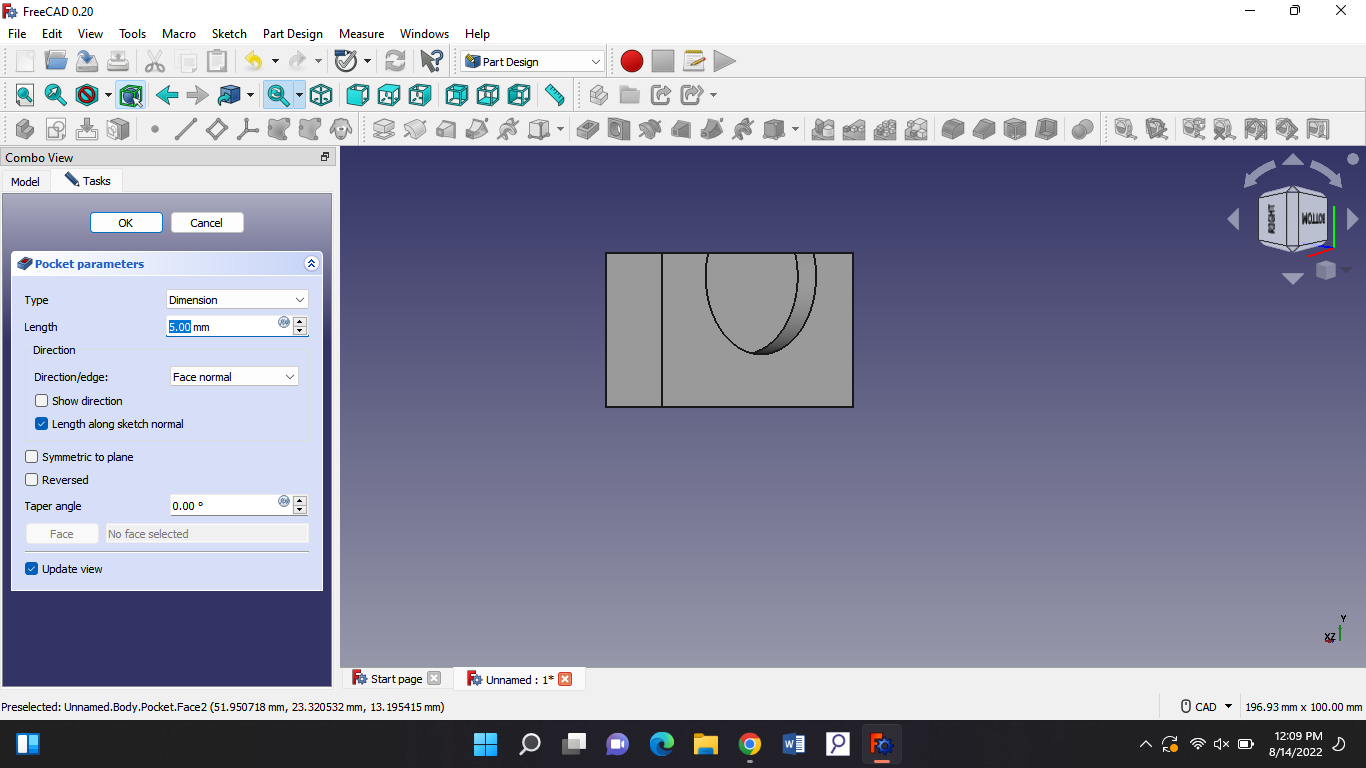
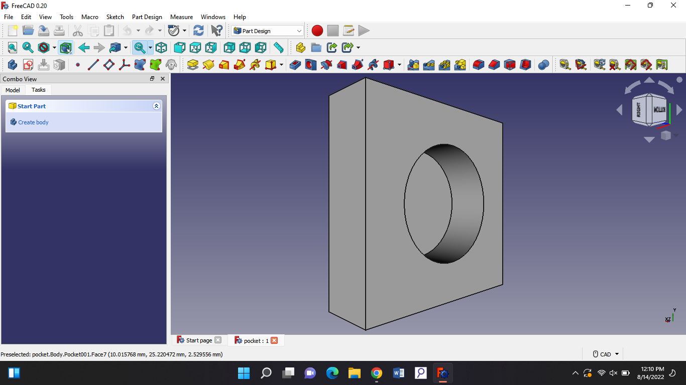
2 make a pocket;
You go to freecad again and make a square and put it in pad mode then you go back to making a sketch after that you make a circle. Then you close the task bar again, you press this feature:
You should be able to see this:
If you put the length higher the whole will increase.
3. 3D designing something and putting it in cura.
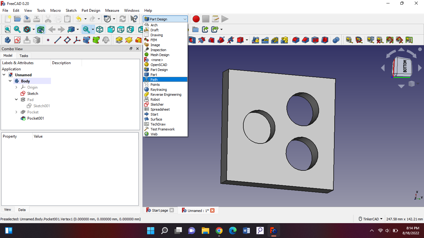
Thursday 18th of August 2022
Objective
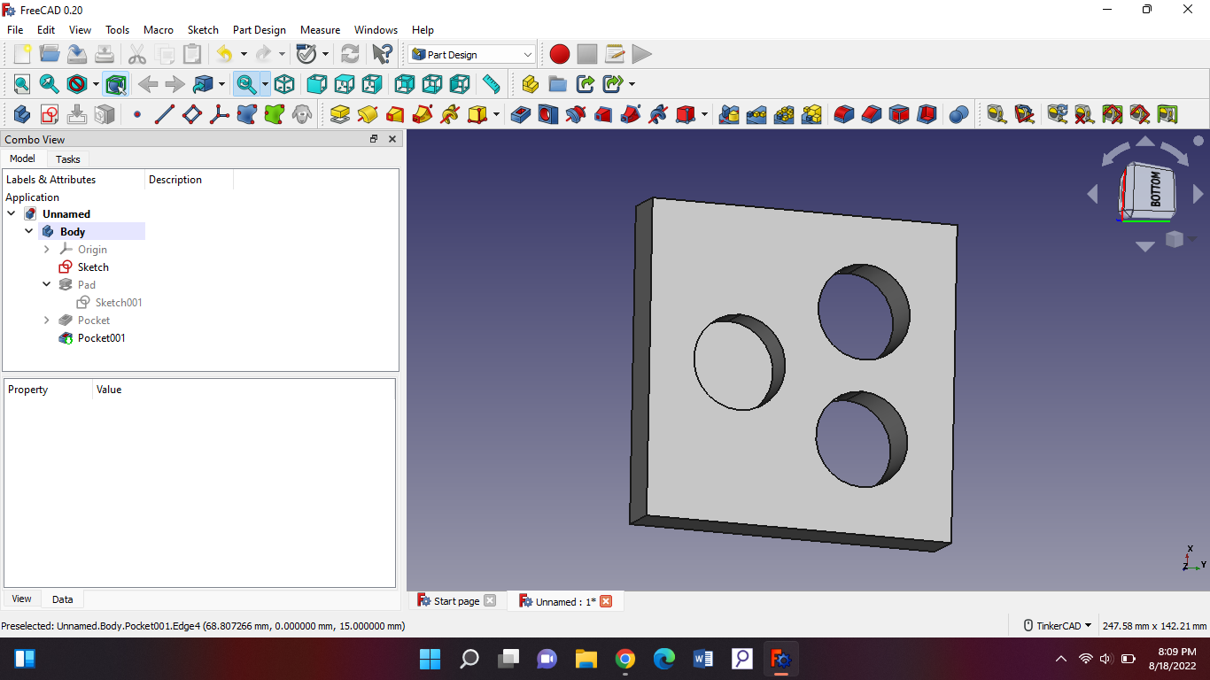
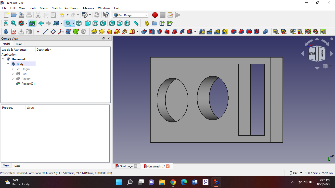
Today we designed laser cutting with freecad. We had homework for the last class and that was designing two holes and one pocket in a rectangle. So first you make a design like this and then we start with the lazer design.
Then we'll add it in path mode:
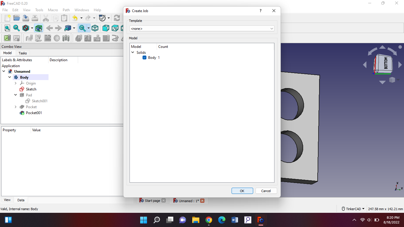
And you're supposed to get new features, then you should press “job”:
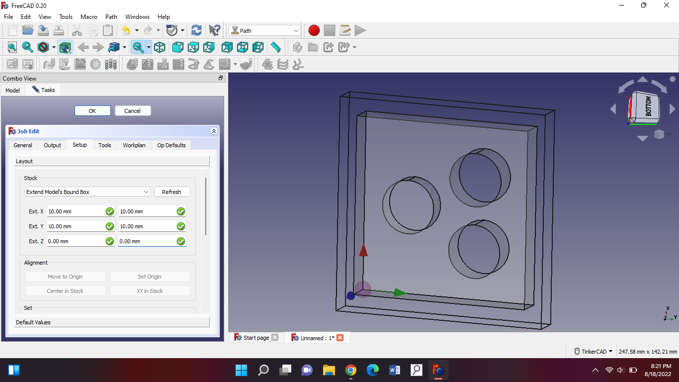
Then you should see this and select “job” and press ok:
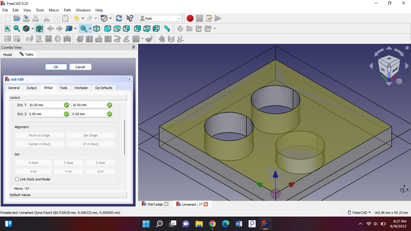
Then you'll get some options and put these stock numbers in there:
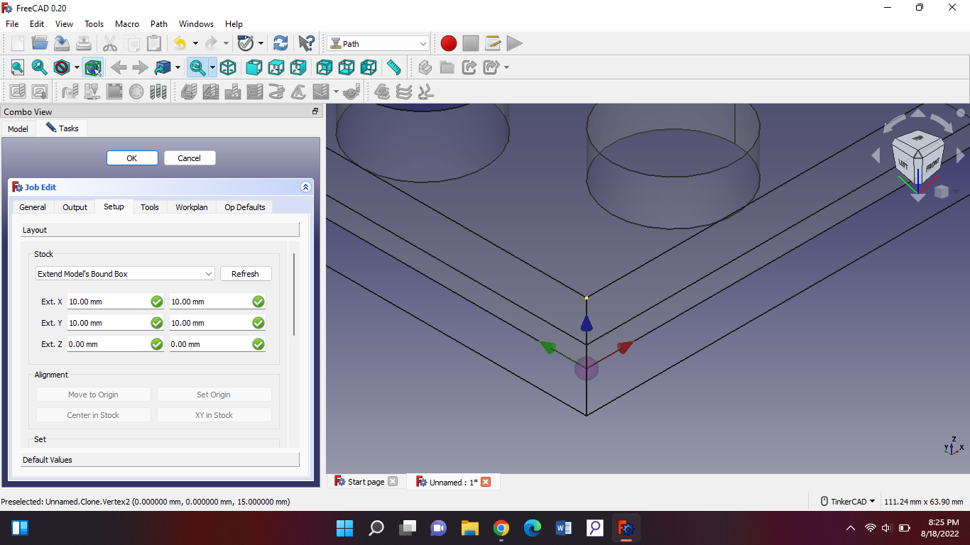
Then you should set the alignment right. You go to this point where the arrows are and then press the top point of the rectangle like this:
When you press the point you should be able to see on the side “set origin”. Now it should look like this:
Then we go on the side to job edit > output. Everything should be like in the picture beneath this. Your file name can be anything but the end should be dot(.)uccnc. Then press ok. Before we create our tool we’ll set our units.
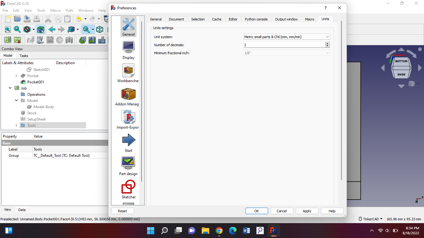
We go to edit> preference > units. Then everything should be like in the picture beneath this.
Don't forget to change the unit system. Then press apply then ok. Now we’ll create our tool.
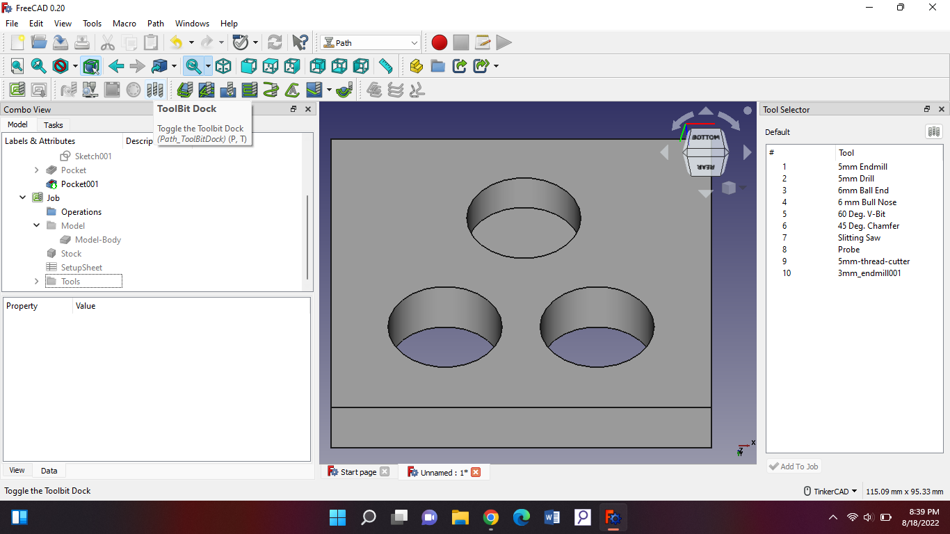
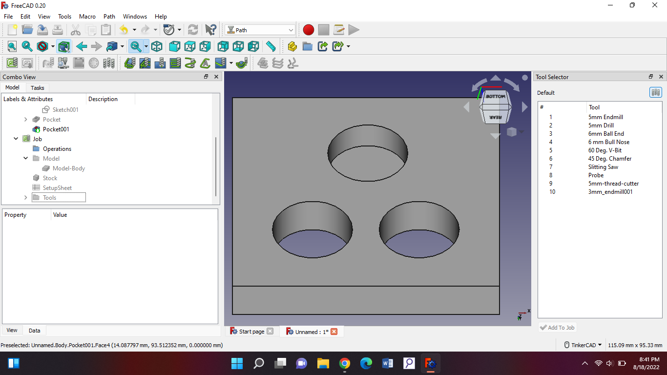
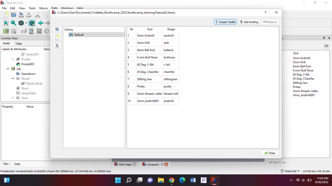
You should press the tool button and get this on the side:
Then we’ll make a new tool by pressing the upper right button on the side that just popped up.
Then we press that and get a new tab:
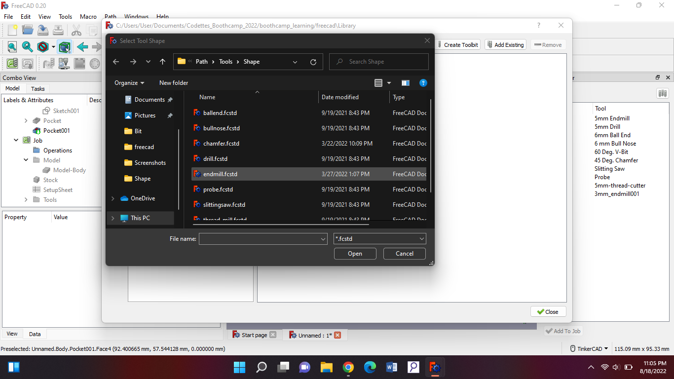
After that press create tool bit, then you’ll get to choose from a few files and we need to take the endmill one:
If you’ve pressed open you should get to make a new file. Name that “3mm_Endmill.fctb”.
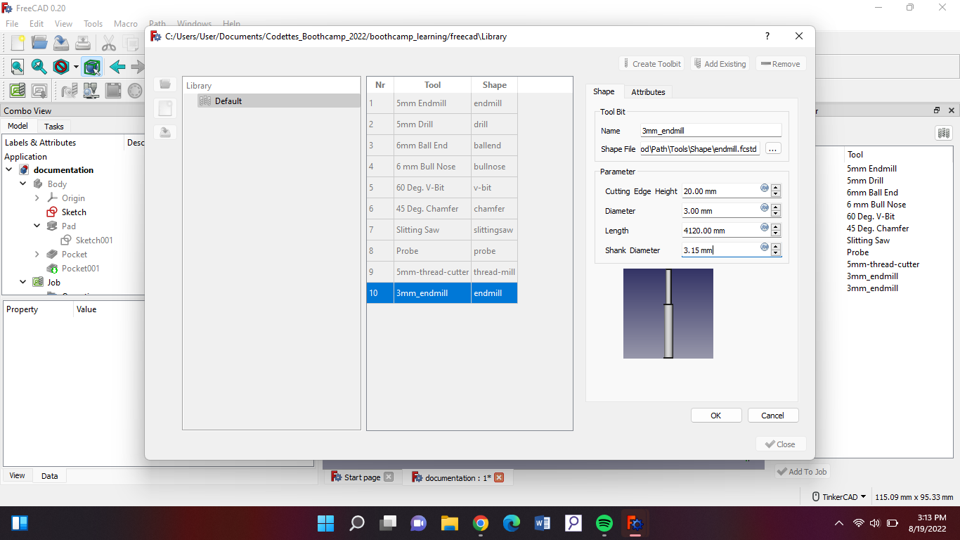
When you've done that you will be brought back to the tool’s library, then you double tap the file you just created and fill the exact same measures that is in the picture beneath this:
Then we’ll go ahead and press ok > close.\
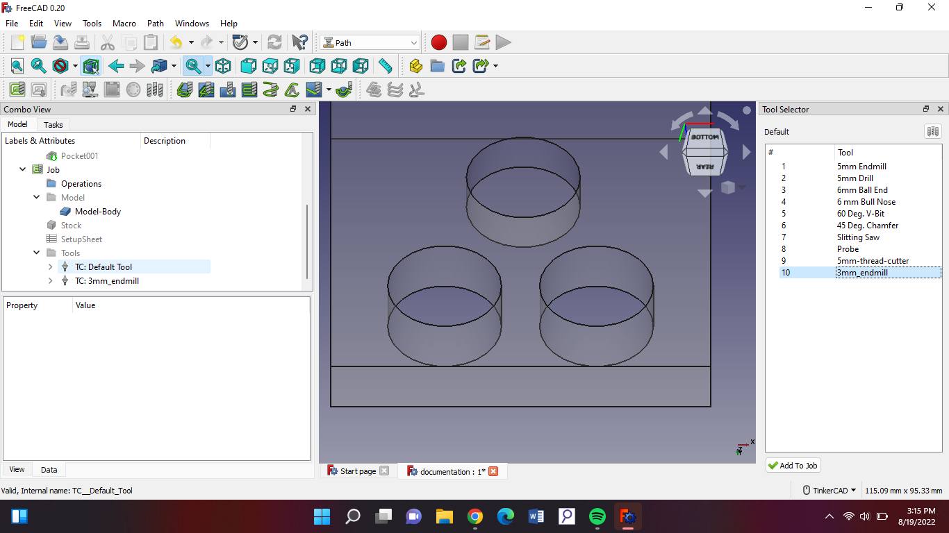
After that you double click the tool you just created on the side and you should be able to see it come in the tools file on the left in your model. The default tool should be deleted.
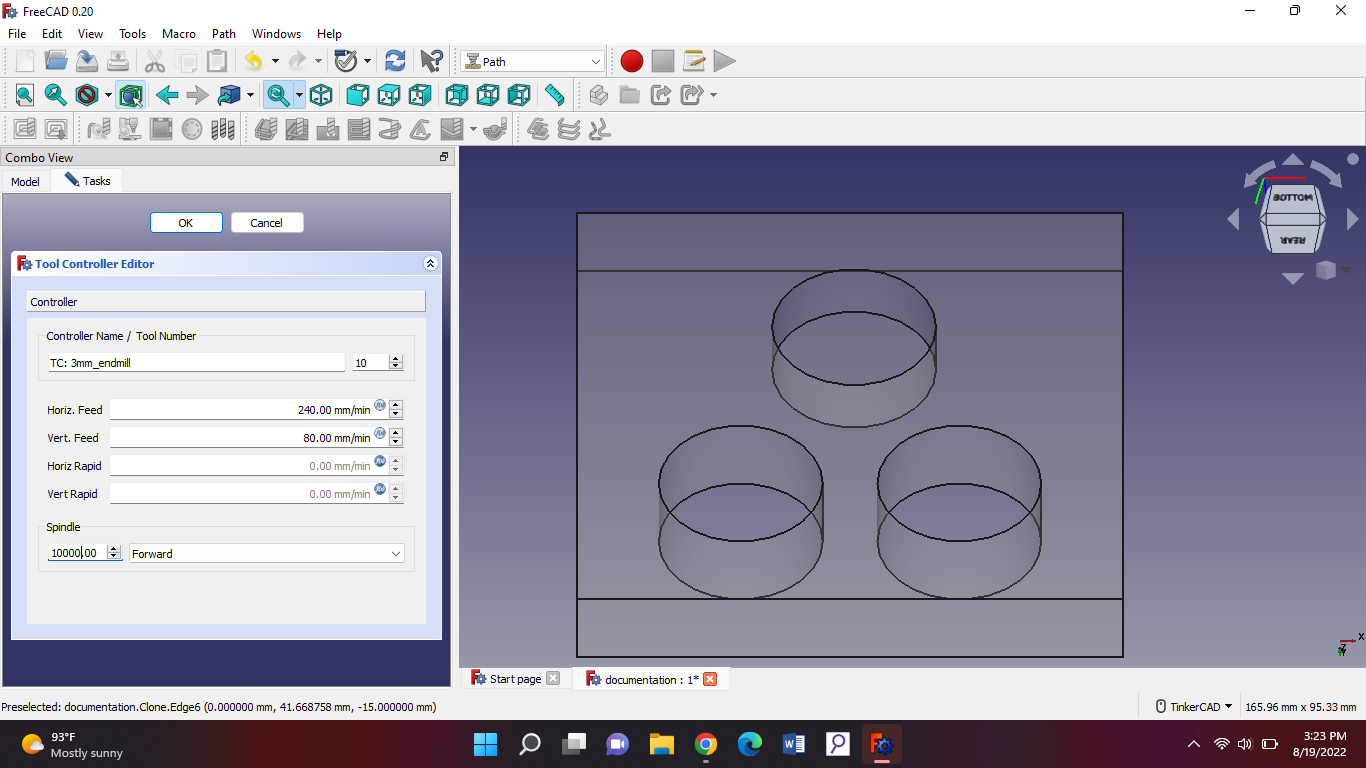
After that you double click your 3mm tool on the left and then you should see the task bar open up with some options for the tool controller. Fill the same measurements i have in this picture:
Once you've done that click “ok”. Now we're gonna go ahead and start to add the settings for cutting the pocket.
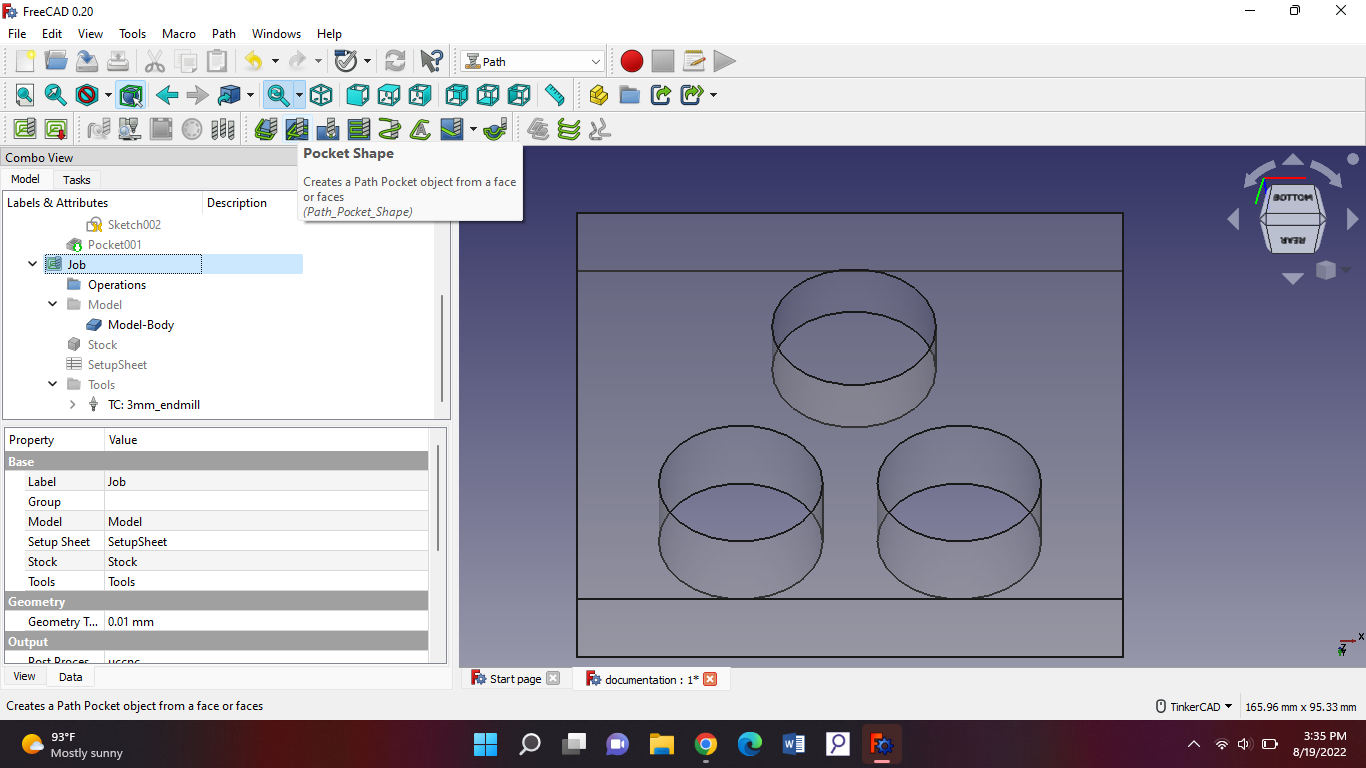
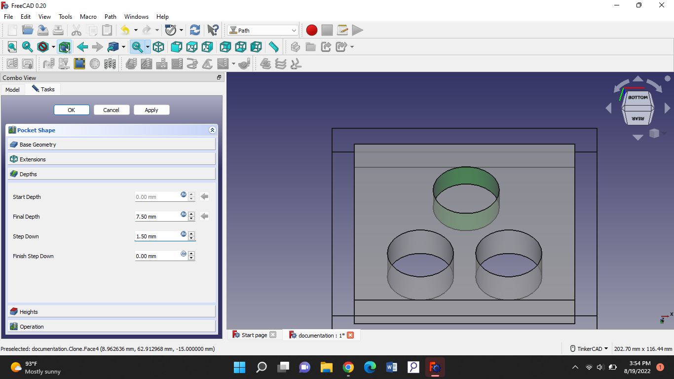
Now you go back to your model, on the left side. Then select “job”. After that you double tap “pocket shape”.
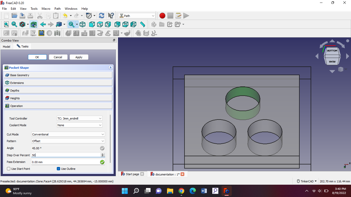
Then you will get new options and for “operation” fill these parameters in:
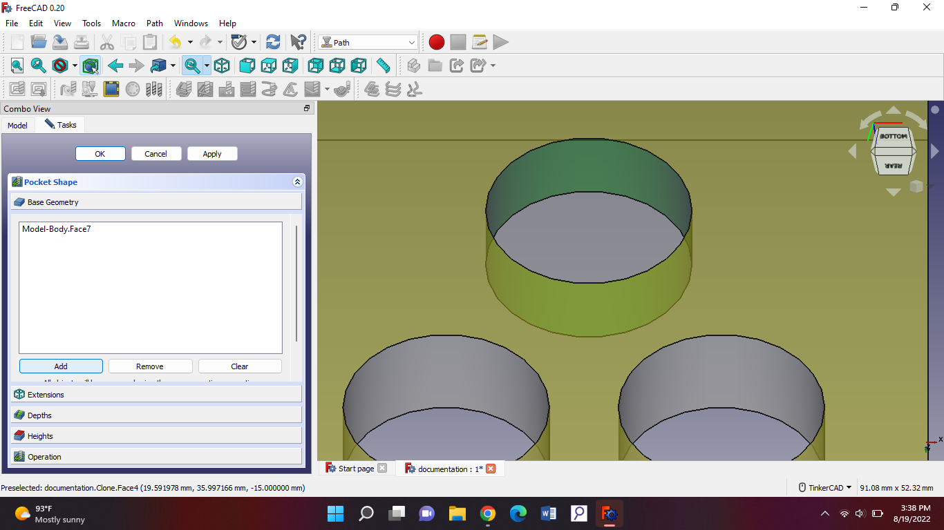
For base geometry, you press that and it should open up. Then you press the lid of your pocket and then select “add”.
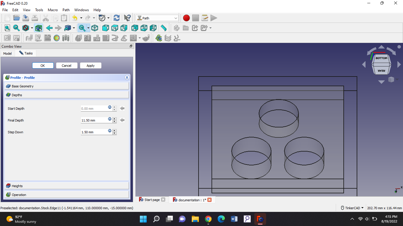
Then we’ll be going to the depths section and fill those parameters in. The starting depth should be 0 because the mill will come from the top and go to a negative position. And your step down should be half of the size of your tool. Then you apply and press ok.
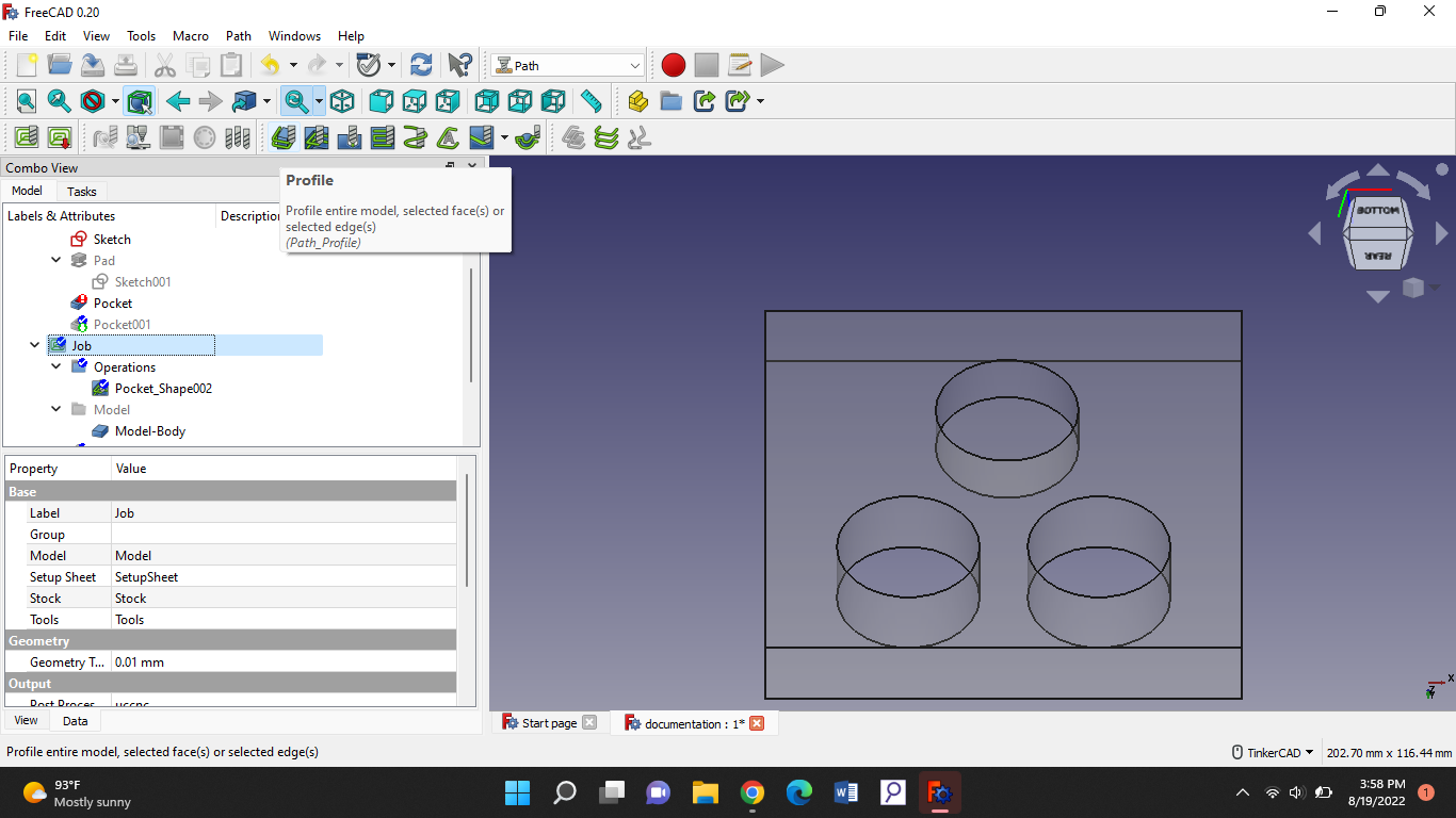
Now we will be creating the cutting for the holes. With the feature “profile”.
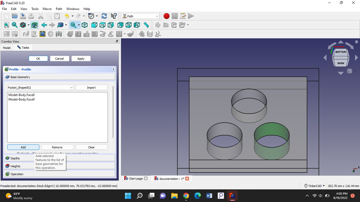
Then you go to the base geometry and add both of the holes' lids.
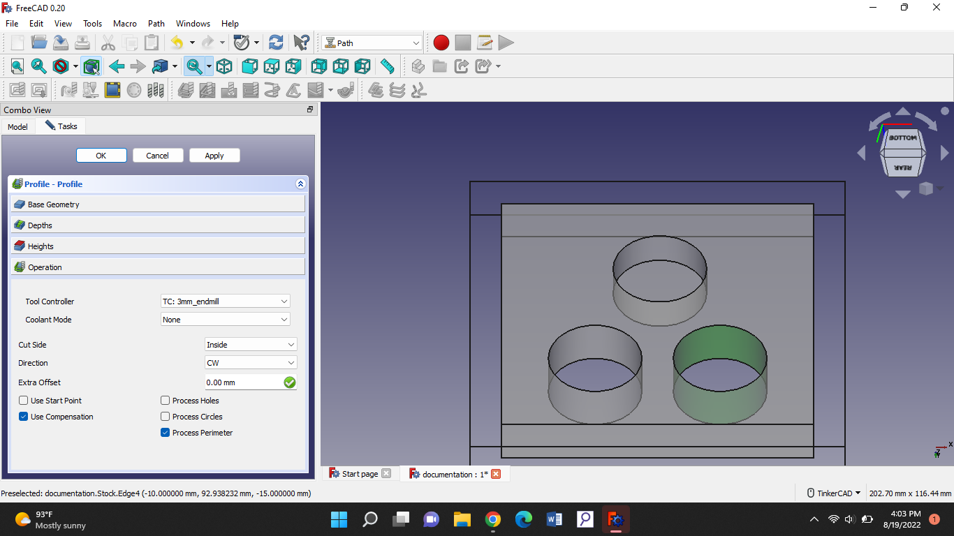
Now we go to the operation section, there we wanna put the cut side to the inside.
After that we’ll go to the depth’s section. The start depth is 0 as always. And for the final depth you have to know the height of your hole, and put the cutting depth a bit higher than that so you know for sure it has been cut. And for the step down its half of your tool diameter.
After that we apply and “ok”.
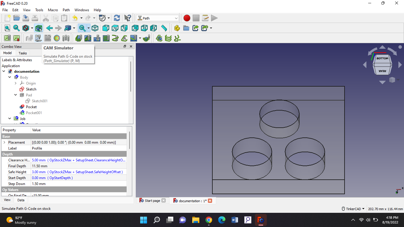
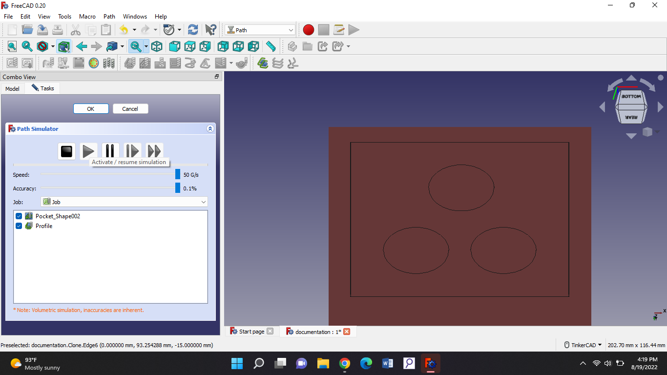
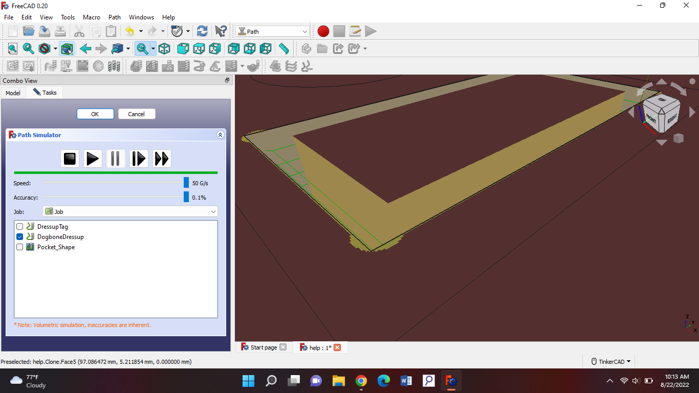
After that we are ready to simulate. This is what you should press to simulate. WARNING: don't have too many tabs open when simulating (YOUR LAPTOP MIGHT CRASH).
Press that and play:
Then we are done for today.
Friday 19th of August 2022
Objective
Today we had to make a slot into the design we are currently working on. The slot should be cut entirely but should leave a bit pieces so it doesn't go loose while still working. So first of all we'll start with making a slot and making a profile for it and add a path dress up. Open up freeCAD!
Start making a triangle and two holes, a pocket and a slot in the very same triangle:
Now you go into path mode and start making a profile for the hole and the slot and for the pocket make a pocket shape. As we did in last class.
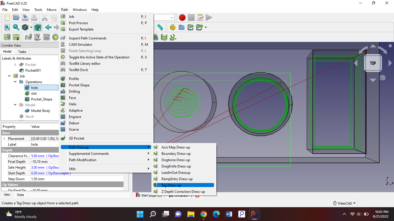
Now we're gonna make the dress up, first step go to the path on top of your page and go to dress up then press tag-dress up.
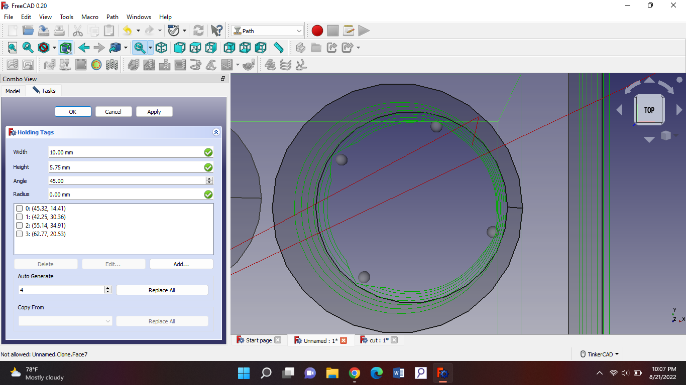
Make sure before you press tag-dress up to have you hole selected on your model. Then put these coordinates in there:
After that you should see these small balls appearing. So what this tag-dress up actually is that it leaves a bit of the material. So where you see the balls, that part is not gonna be cut. So it doesn't fall off while the machine is busy cutting the others.
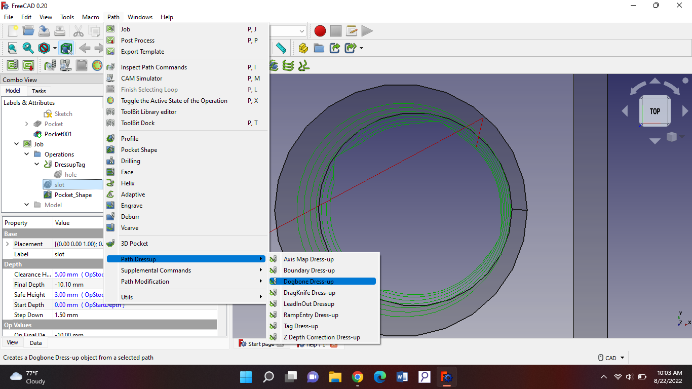
Now we're going for the slot but this one is gonna be a bit different because it's a triangle. For the slot we're gonna leave a bit of material but at the points they'll be cut in the forms of balls so we are sure all of it is cut. So do the same thing, make a profile and in that profile we go to dress up but, for this one were gonna choose dogbone dress-up:
When you're gonna press that make sure that you have your slot’s profile selected. When you have pressed your dogbone you should see small kinda looking pipes appearing in your triangle. Now when you have simulated it you should see the sides of the triangle have been cut differently.
Mistakes
Not having my file selected before making a dress-up.
Thursday 25th of August 2022
Objective
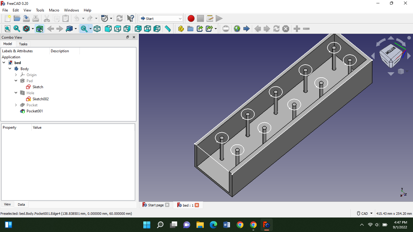
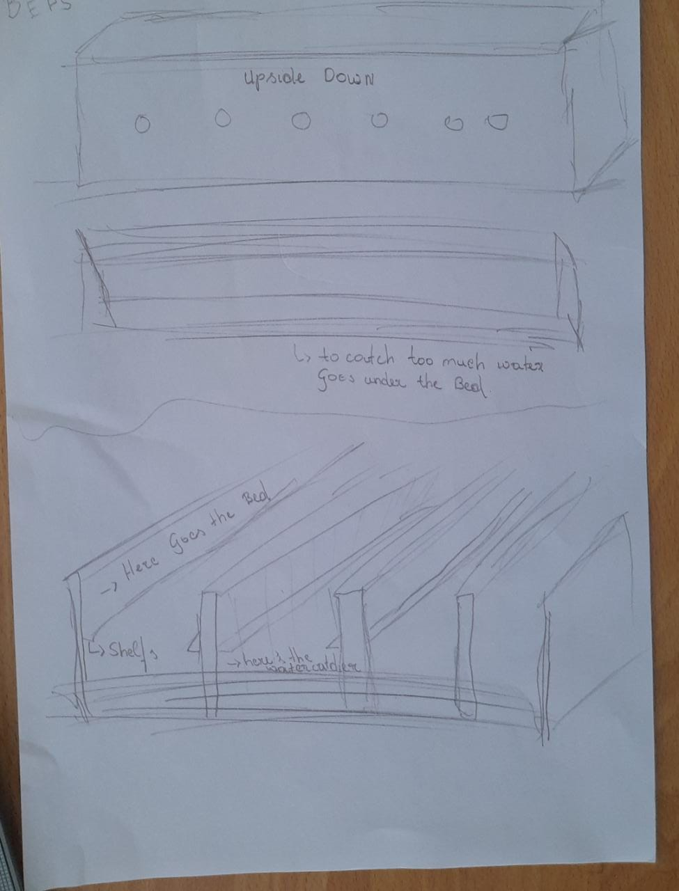
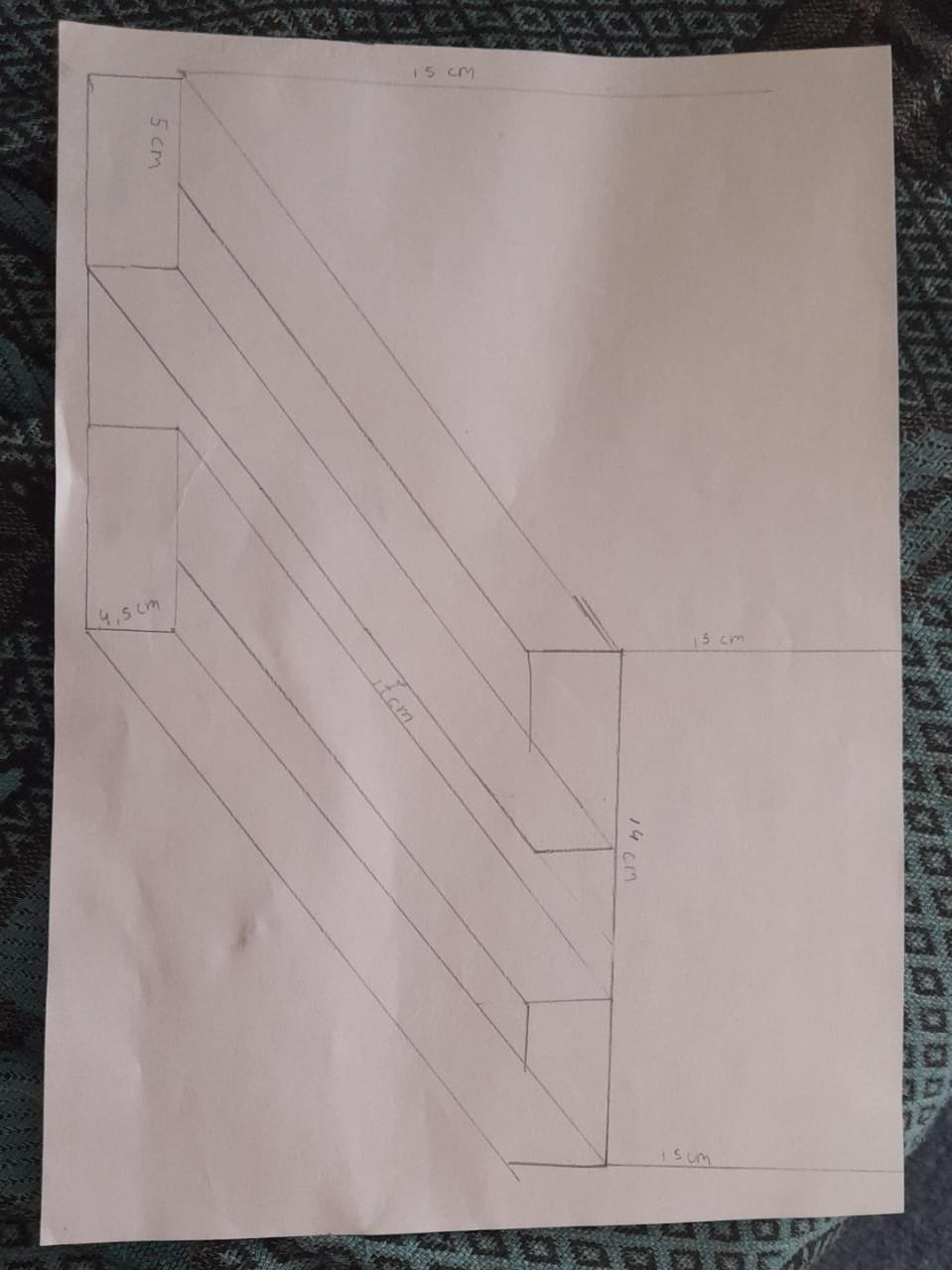
As homework for today we had to make a design in freecad for our final projects. And i made this:
This is the bed part of my kit. But the sticks you see in the middle should be holes. I made it as a hole but turned out as sticks. And these are a few sketches that i made:
Thursday 1sth of September 2022
Objective
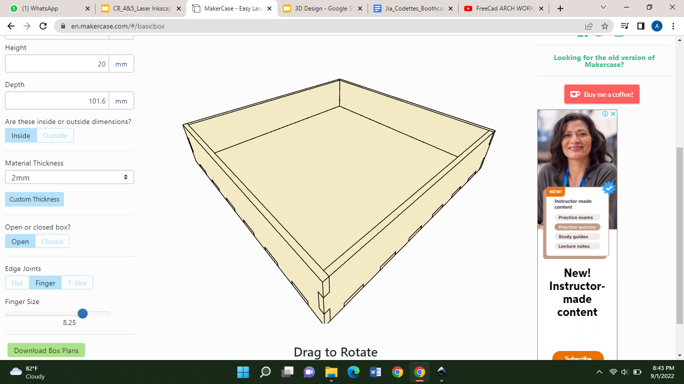
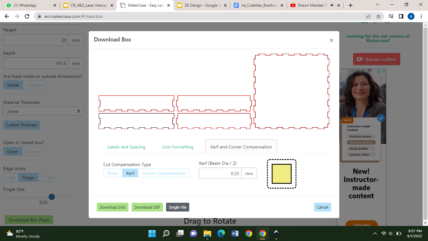
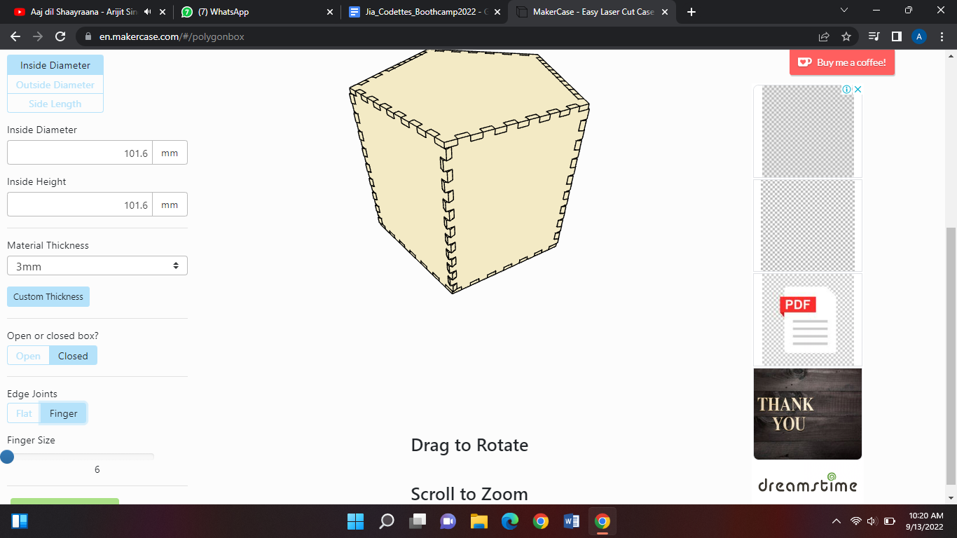
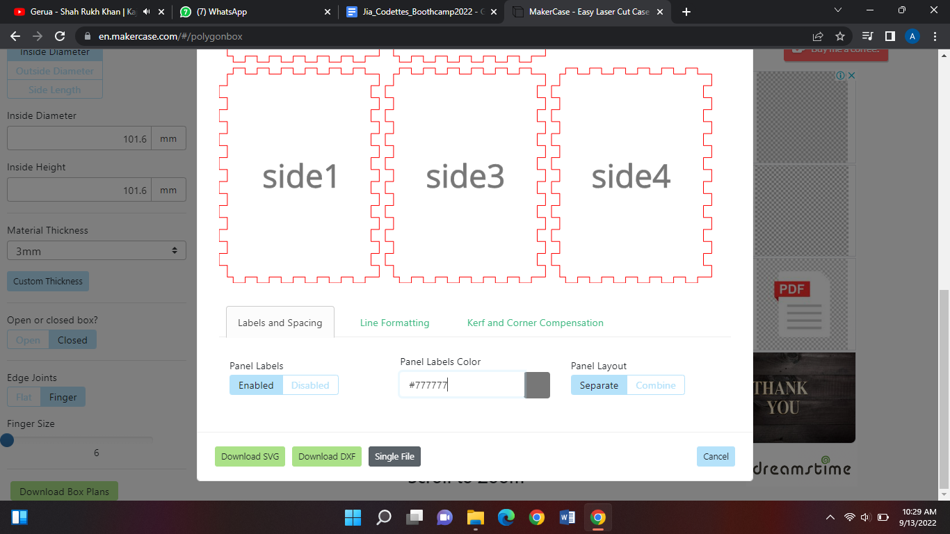
Today we're gonna design laser cutting. To do that you have to have inkscape installed. After that I went to makercase to choose my box. And why we use makercase is because the boxes have edge joints and it's easier with makercase. So you just have to export and import into inkscape. After I chose my box I changed the parameters to mms. Then I adjusted my height etc.
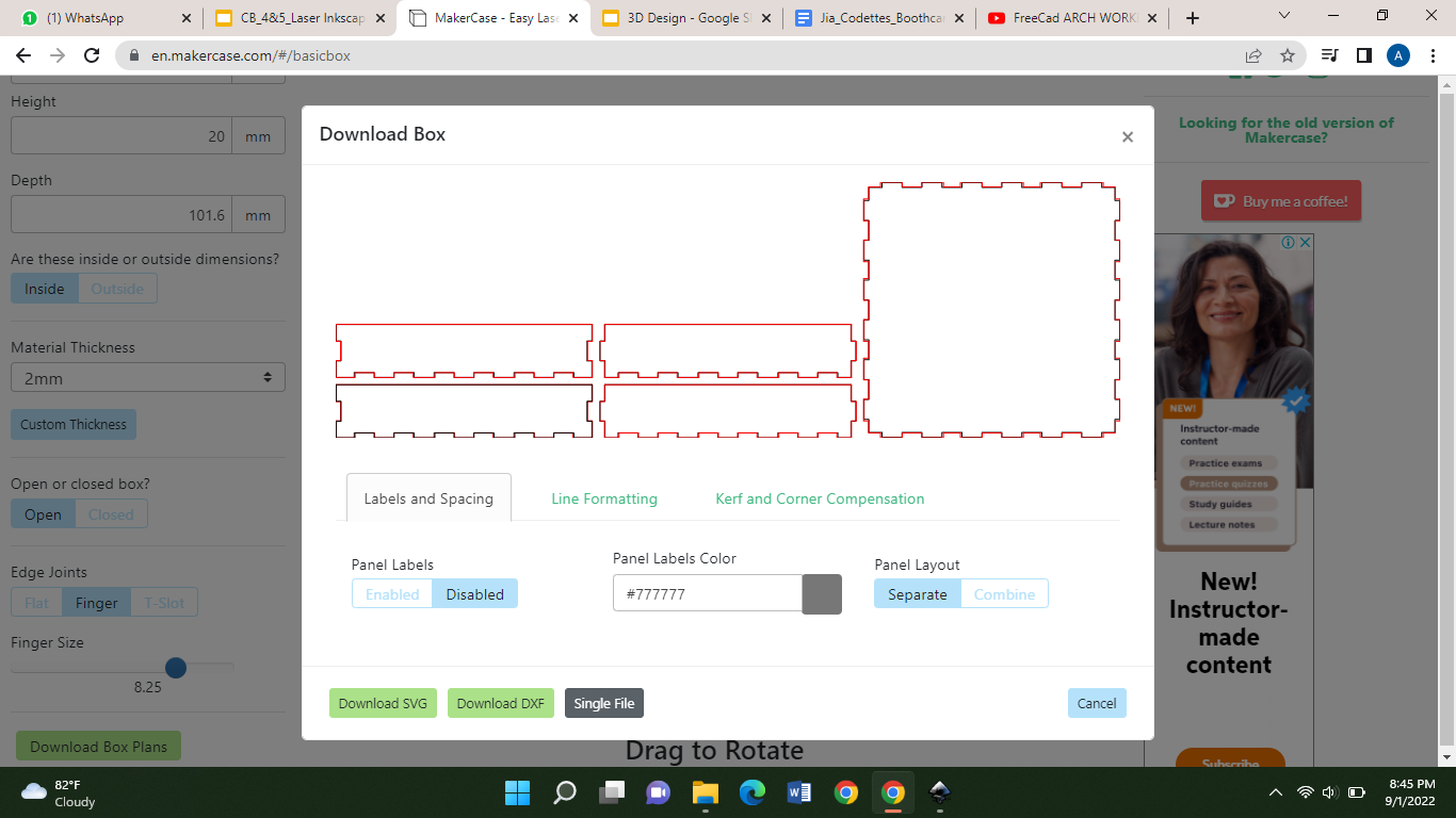
To have more edge joints you can decrease the finger size. Then you click the download button and you should get these options:
Be sure to disable the panel labels. And the panel layout is separate. The cut compensation type should be kerf, then download it in SVG type:
Be sure to store your file in the right place and not in the downloads.
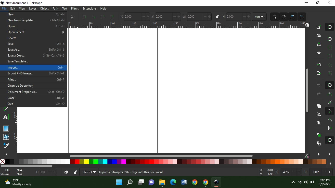
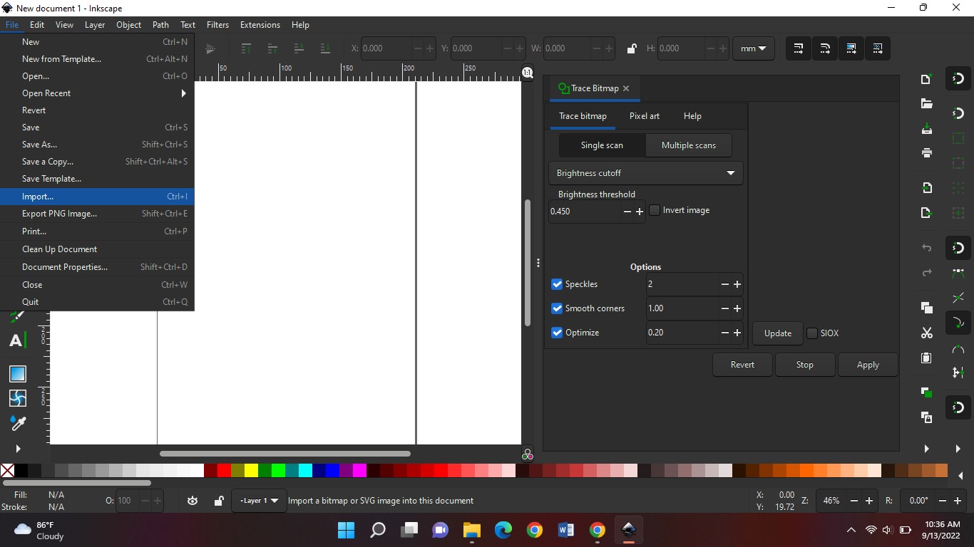
When done open inkscape and import it, file > import
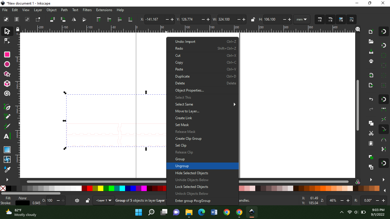
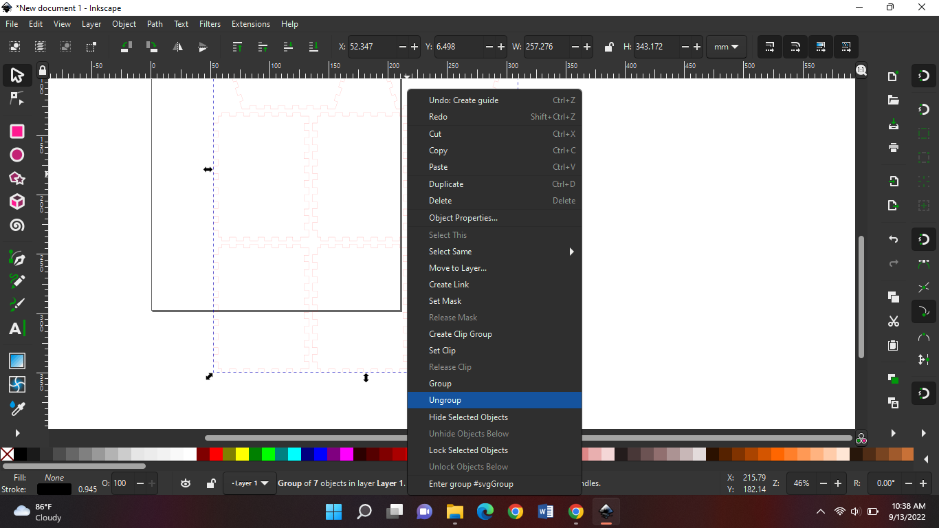
When imported, ungroup your design:
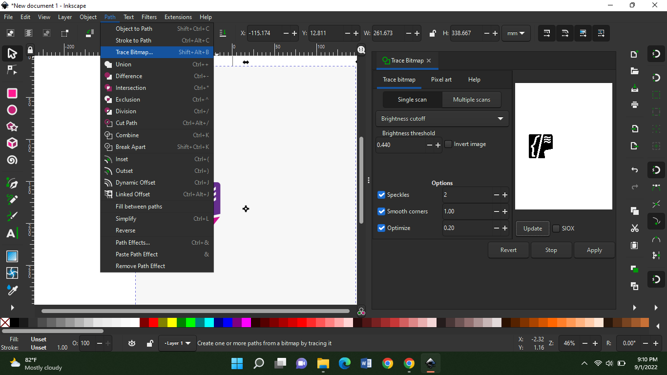
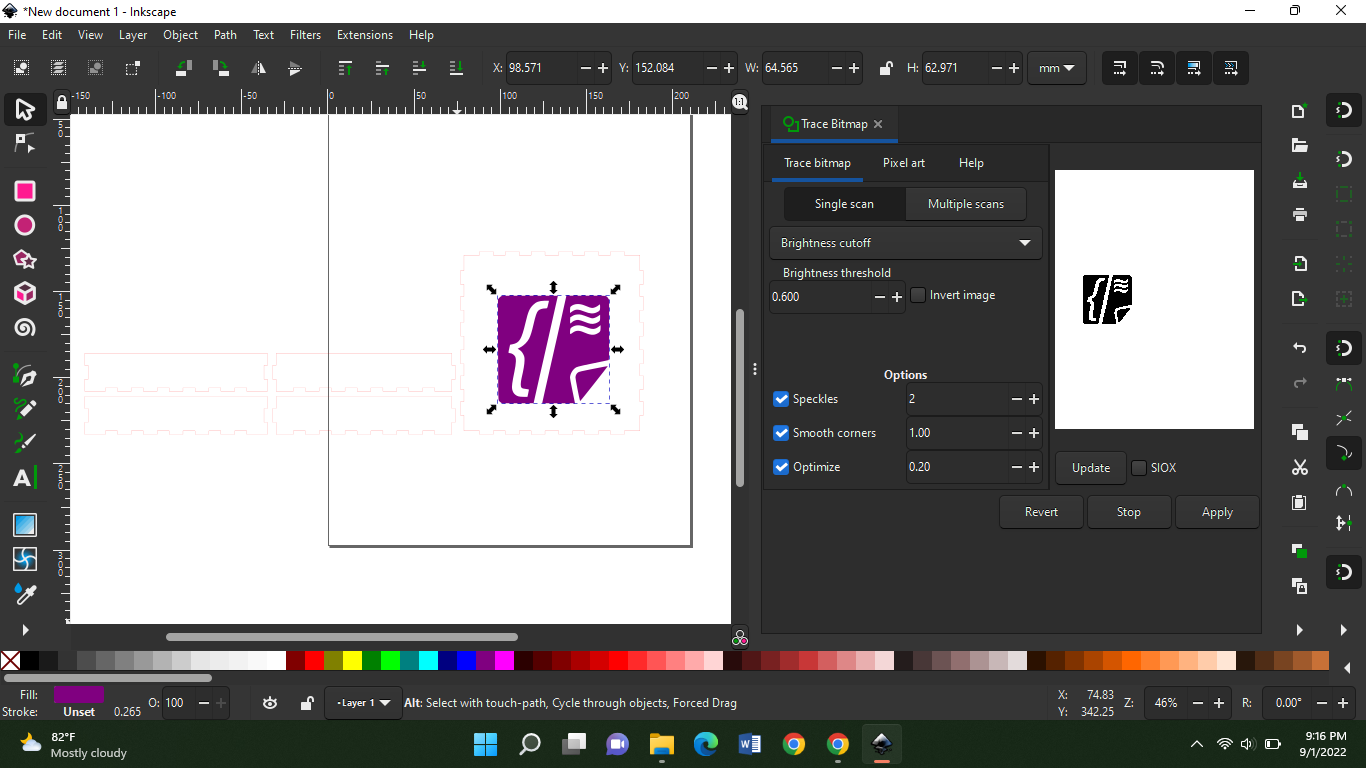
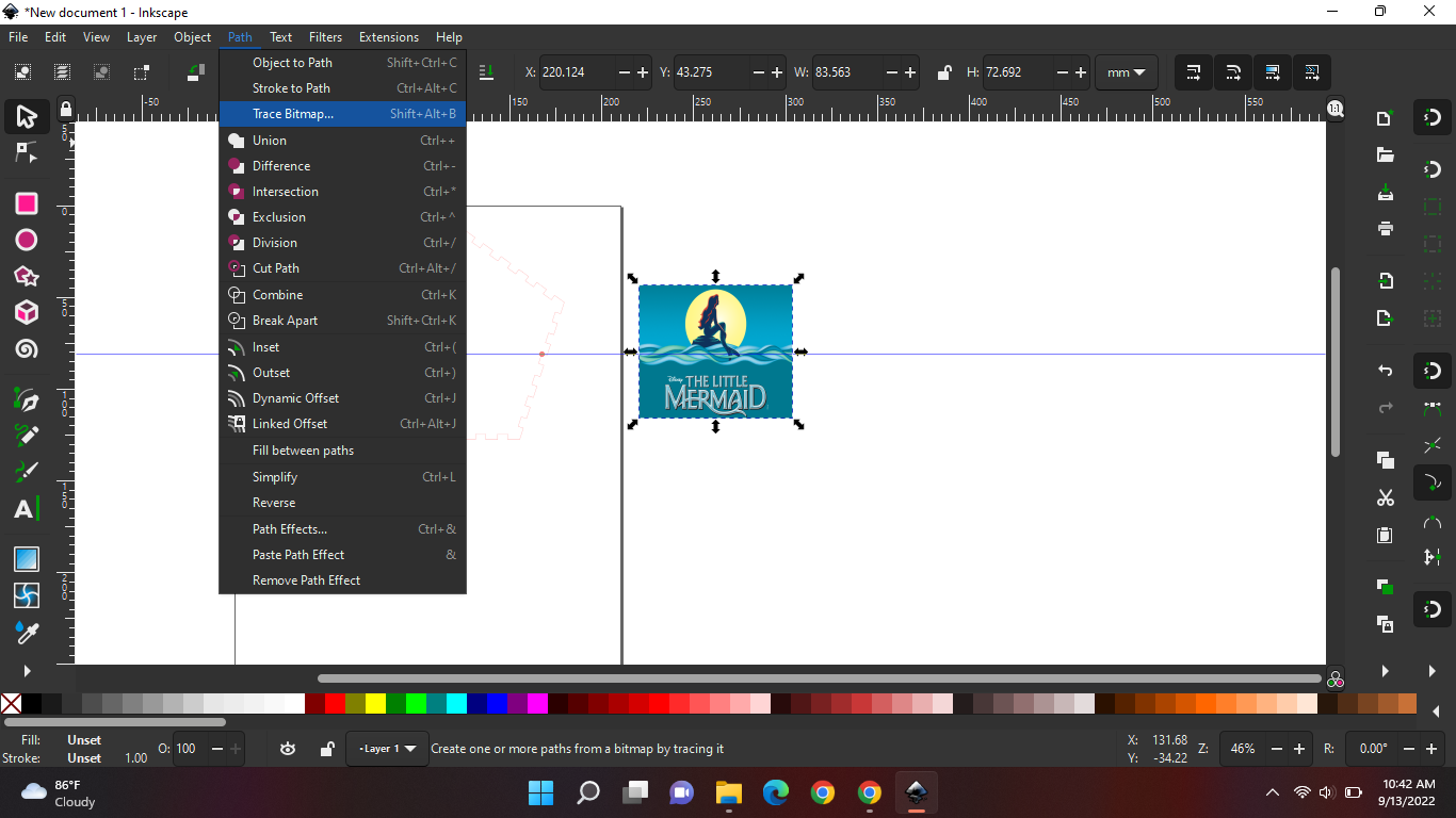
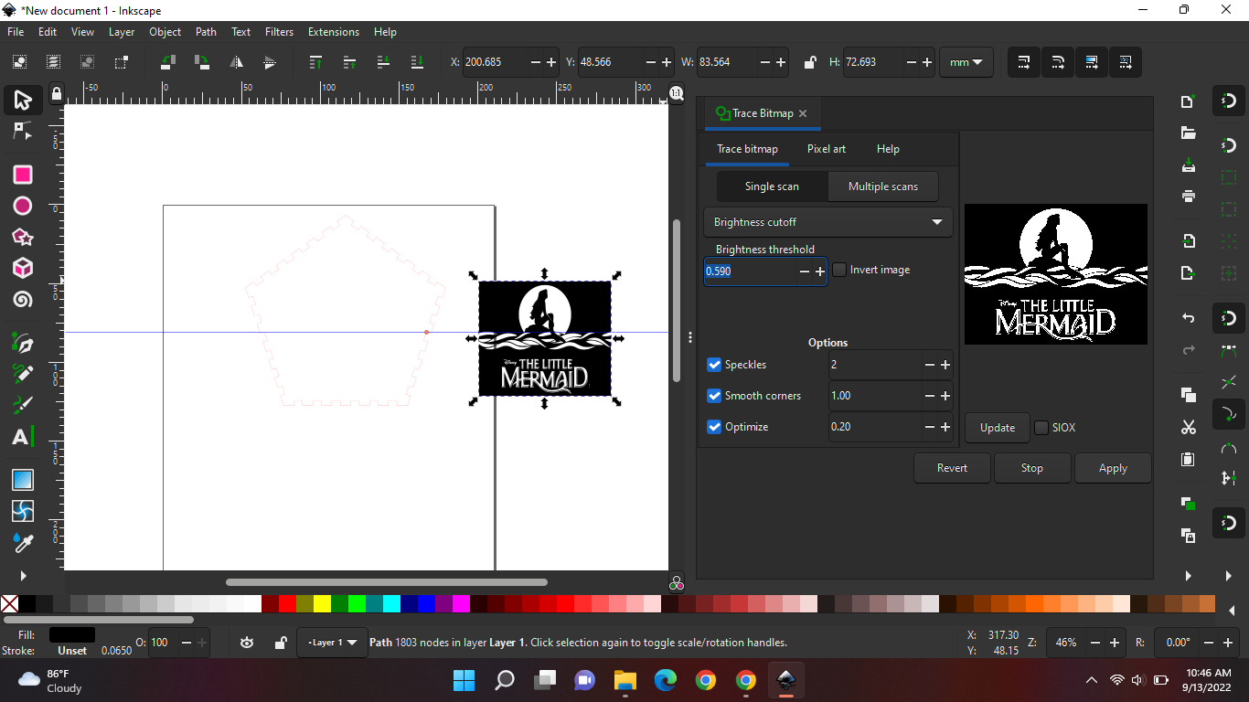
Download a pic, I have the codettes logo. I will import that into inkscape then select the picture andgo to path> trace bitmap. Select shift>ctrl>f to get the menu.:
After that you click update, you should see the picture pop up on the side of the menu. In the picture above you should see that a corner of the picture isn't coming, to fix that you increase the brightness threshold a bit then press update and you should see the corner appearing. Then you click apply. And it should appear on your workspace in black and white.when you move the black and white picture you'll see the original picture behind it, you can delete that on and put the black on on the box where you want it.
You can give the picture a color. Just select the picture and choose a color from underneath the workspace. Then you save the file as SVG.
Homework:
Today's homework is to create my house that will be used in my kit.
Mistakes
Be always present in class.
Friday 2nd of September 2022
Objective
Today Mr. Theo went over a few slides about the laser cutting machine. And how it works and stuff. So tomorrow we are gonna use that and learn how to control everything. Here are the slides.
Saturday 3th of September 2022
Objective
Today it's my turn to try to cut something on the cnc. First off we design something in freeCAD just like in the previous classes. I designed a hole with the tag dress up. When you're designing don't forget to put the height/thickness of your material. I measured mine in the lab and it was 11 mm. So I went to the pad and changed my length to 11mm. And never forget to add paths, or else its not safe to cut it like that. It might spat in your eye.
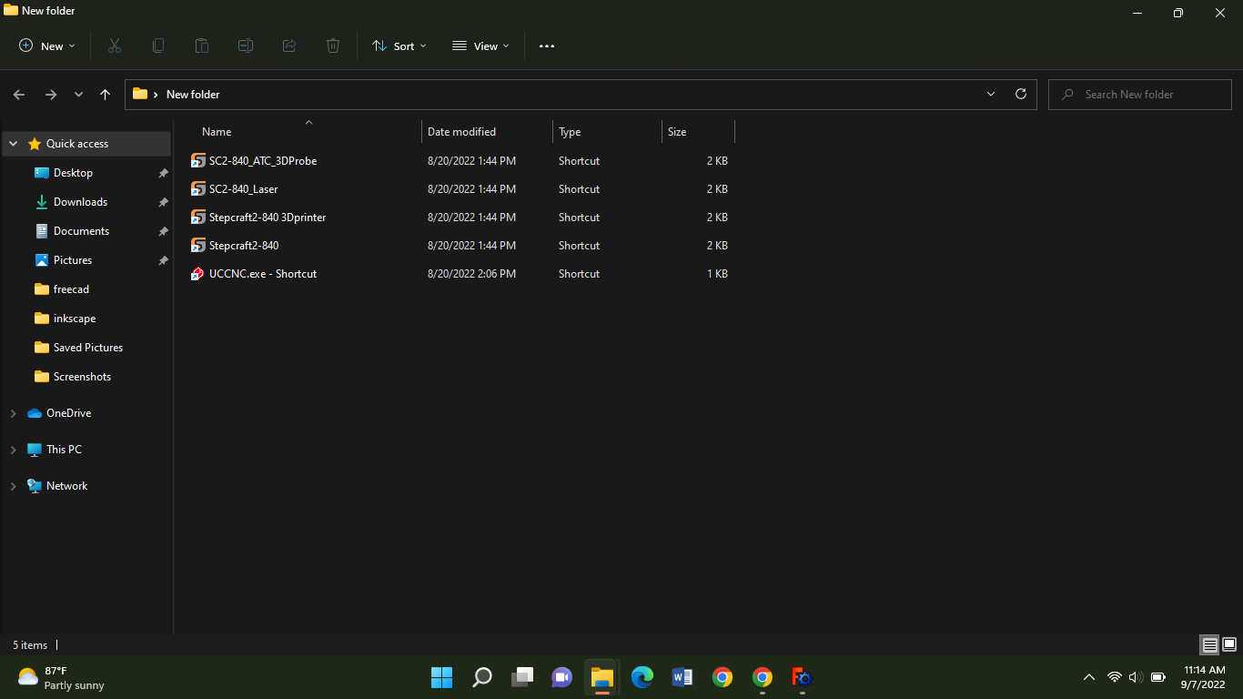
When you buy the machine they give you the tool with it to download on your laptop. So I got it from the lab manager and downloaded it. For this machine we use: Stepcraft 2-840.
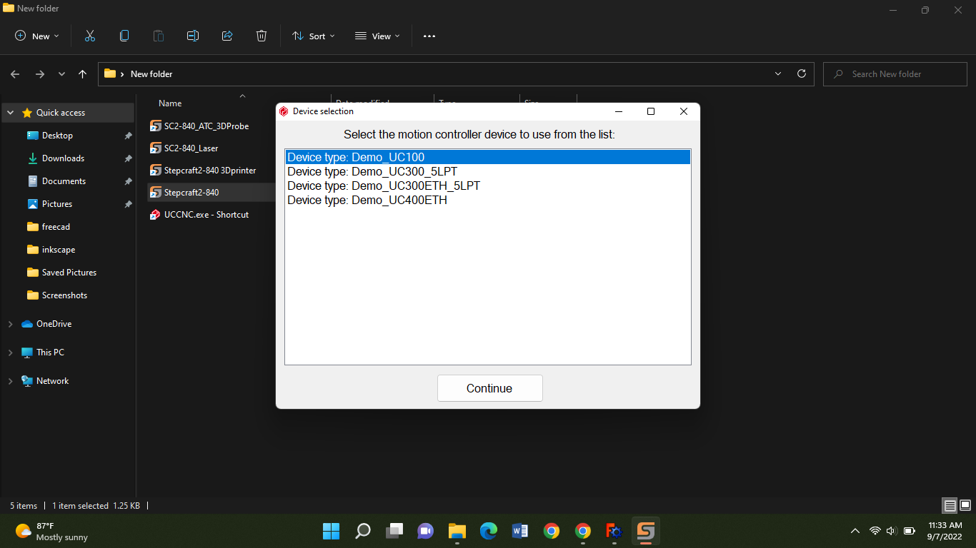
Then you will get this and select the first one cuz thats the one we have in the lab.
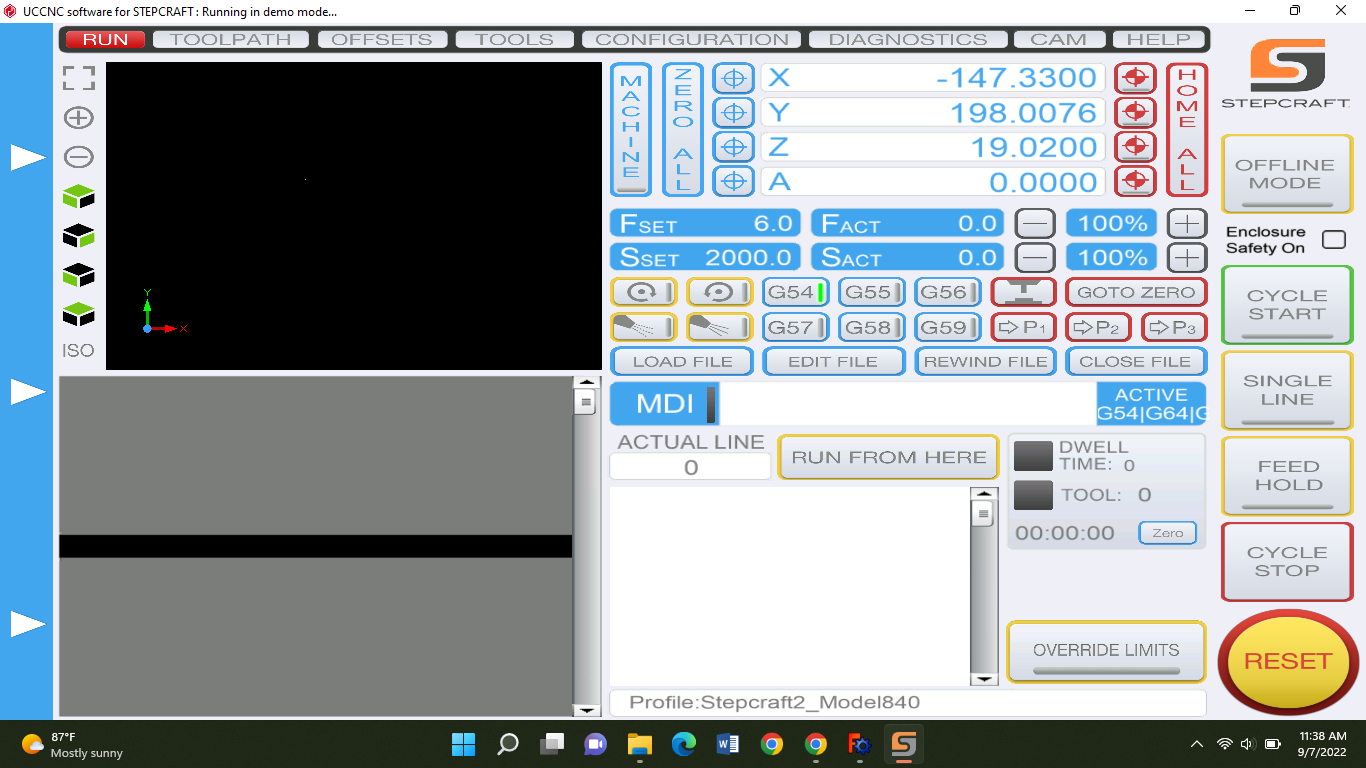
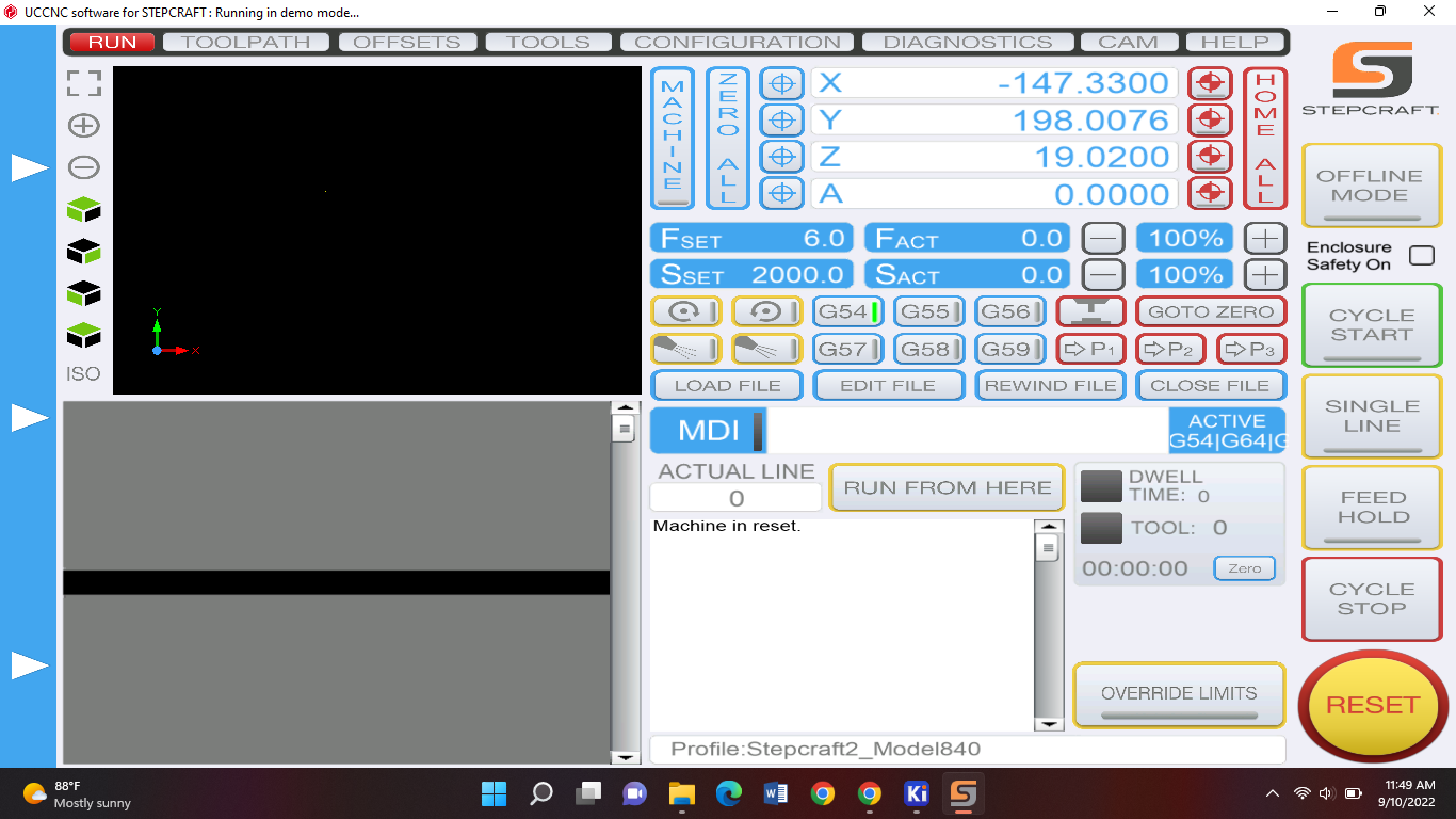
The machine has a cable that is connected to the machine and the other side to your laptop. At the end that is connected to the machine has 2 leds. When connected to your laptop the led should turn blue that means you're good if not check your connection. You should get this when you selected your device and pressed continue:
Then you should press the reset button or else it will save the data that WAS used before. Then you should see your X, Y, Z and A should become 0.0000.
Then you should put your drill on a place where hasn't been cut yet with these arrows:
Then you select the load file and enter the file you want to upload. After that you go to edit the file and check the gcode just in case something is wrong. Remember your F should be 10000 found in the gcode. After that you pring your drill to the place you want to cut and put Z on zero:
Press the blue button right next to the z. The you press “cycle start”:
Then it will start drilling but, you have to stay there if something goes wrong.
And vacuum the dust it creates. If something goes wrong press “cycle stop” immediately.
Lasering
For lasering we had to install Inkscape. So we wanted to laser a piece. So for that you can use makercase. In makercase you can choose already made boxes for you and take one of them and adjust the height, length etc.
Also make sure that your edge joints are finger, so it is easier to put together. After that you press “download box plans” on the bottom. And you should get this:
Here you should disable your panel labels. At the kerf and corner compensation the cut should be kurf. Then you select “download SVG”.
Then you open inkscape and import the file you just downloaded in there.
File > import
Then you ungroup the whole thing:
Then you keep the part you're gonna laser and delete the rest. After that you import a image you want to engrave on it. Then you select the image and press path > trace bitmap
After you select that you should get a few options on the side there you press update and lower or set the brightness threshold to get the perfect image. When you are lowering the threshold keep pressing update, when youre done select apply:
You should see the image appear black and white after you've selected apply. Put that image on your box. When you move the black image you should see the original behind it. You can delete that cuz we won't be using it. After that you're done and can save the file. Then you go to your machine and connect your laptop and…
Friday 8th of September 2022
Objective
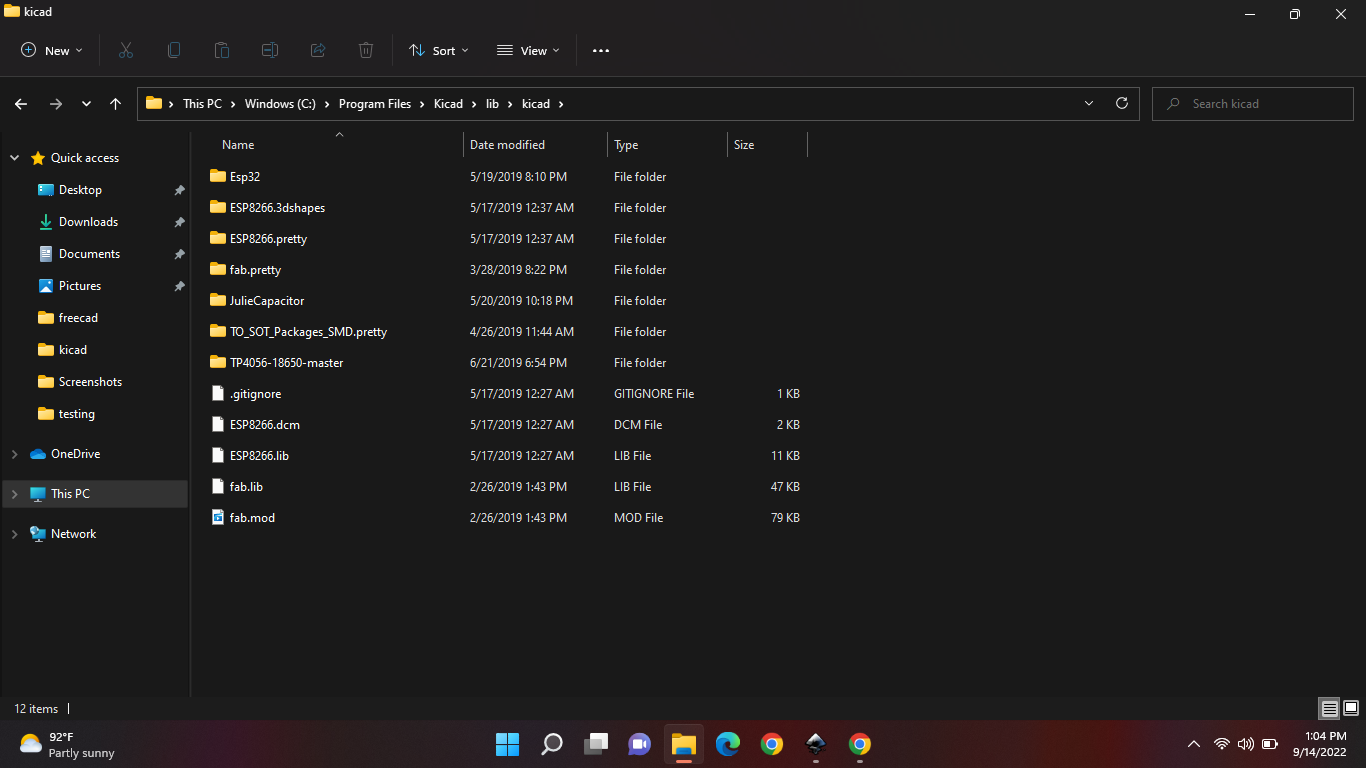
A part of the bootcamp is that we make something like the arduino but from scratch.and we will make that with the help of kiCAD. So in kicad we will make the board with the components and then engrave that. Then we will solder the components. You will also need to download the components we will need in here. Download it all then extract the file. This is how your folder structure should be:
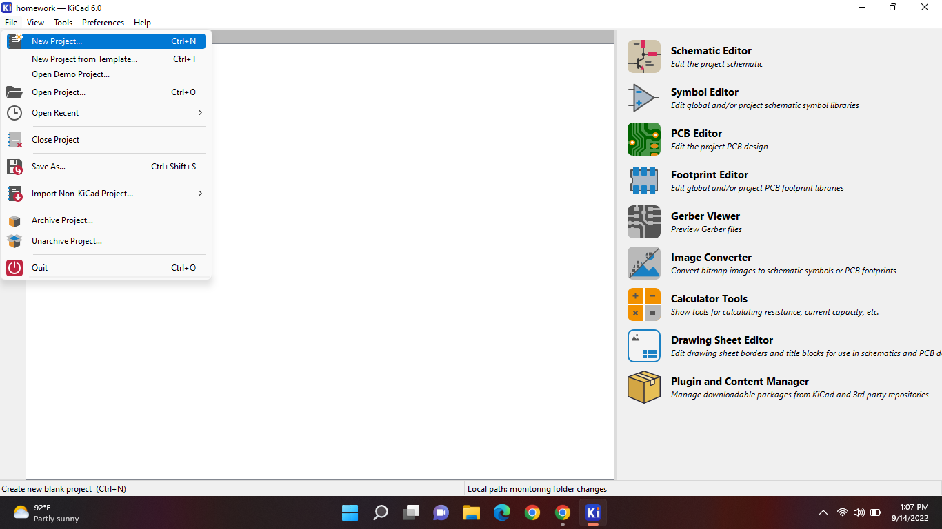
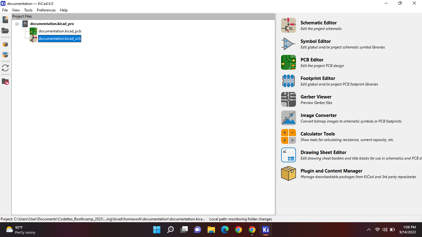
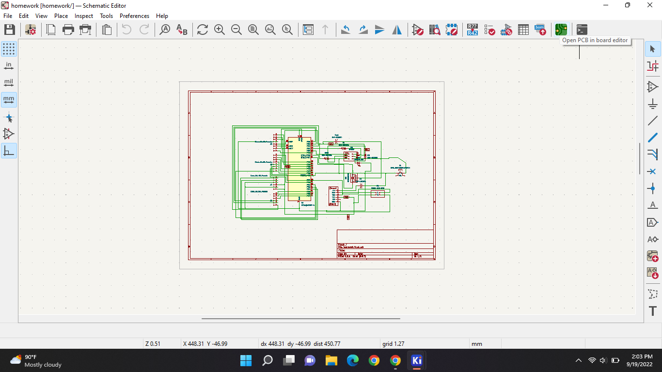
Now go to kiCAD and create a new file:
After that, name the file and save it somewhere you want. Then you select to sketch it. (the second option, not the green one)
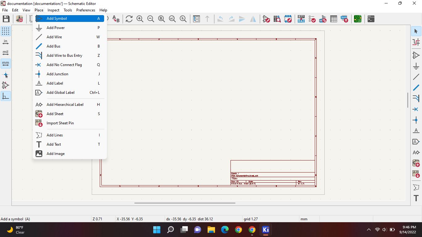
After you've selected that you should get a work plane, then you go to place (on the top) > add symbol:
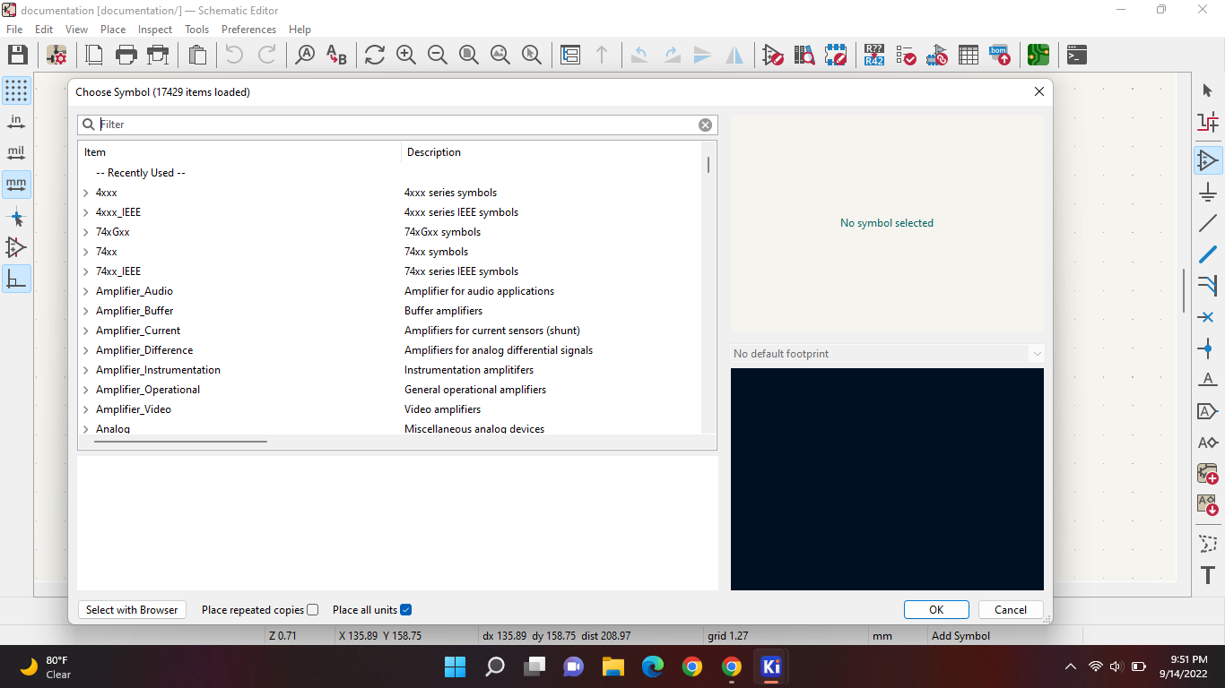
You should get something like this if you've selected that:
Scroll into that until you find a file named “fab”. If you haven't found it, check this file.
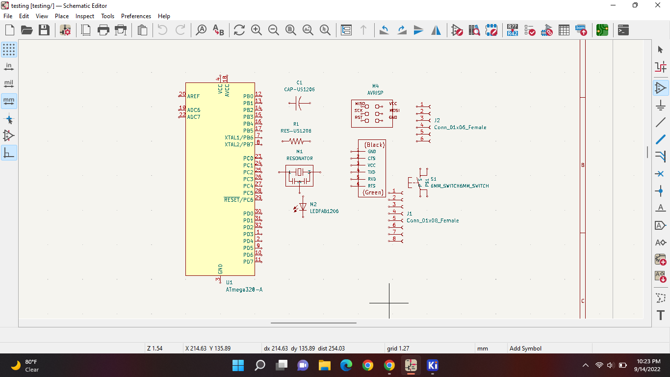
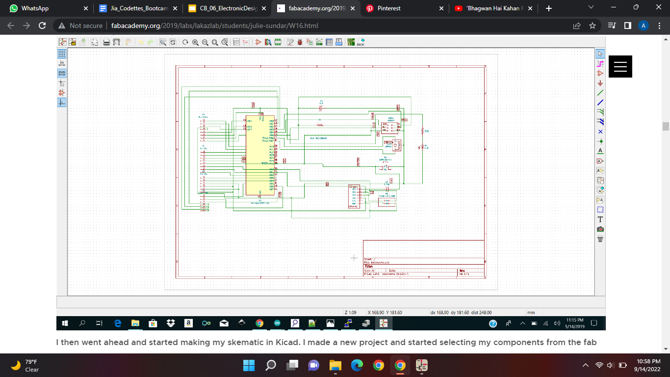
Now you need to go into the fab library and you should see a lot of symbols. Now i need you to add all of these symbols on your workplane:
When you have all of that on you work plane it should probably look like this:
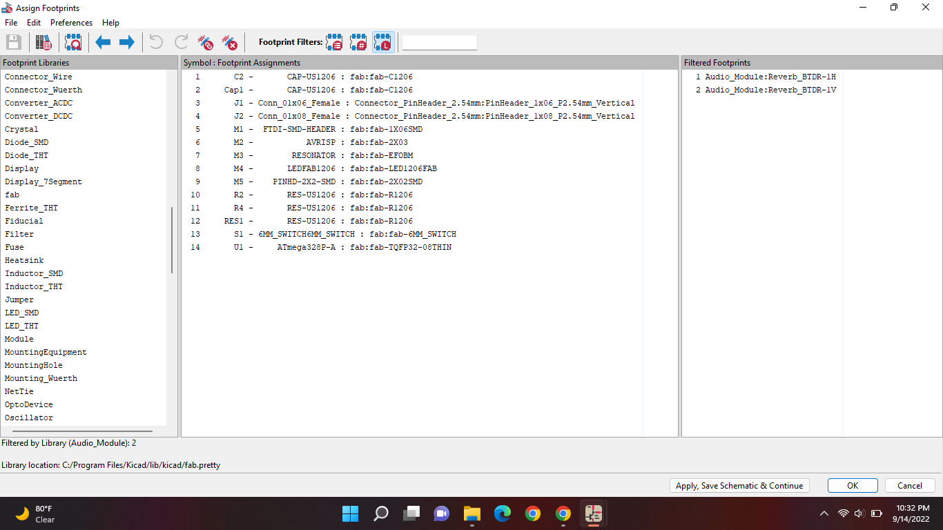
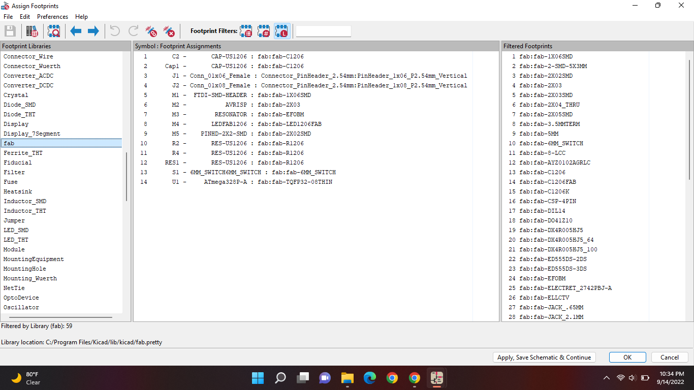
Now we will add footprints, which is the most important part. To add footprints go to this little icon on the top that says assign footprints:
Then you should get this popping up:
Now you scroll on the left until you find the fab file and press 2 times you should see other things popping up on the right:
Now you should select one symbol (from the middle) then select an item on the right. And these are the items that should be together:
For example:
You have selected “CAP-US1206” from the middle then you should find “fab-C1206” from the right.
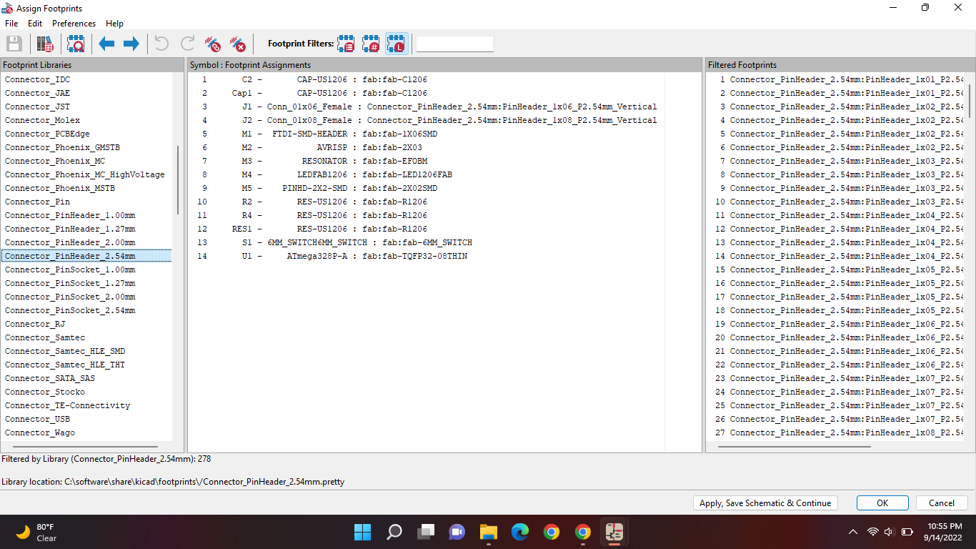
For the Conn_01*06_Female and Conn_01*08_Female you won't find these in the fab library. For these you should go to this one. It's on the left.
Then you should see items pop up on the right, now you need to find these: “Conn_01*06_Female and Conn_01*08_Female” in there.
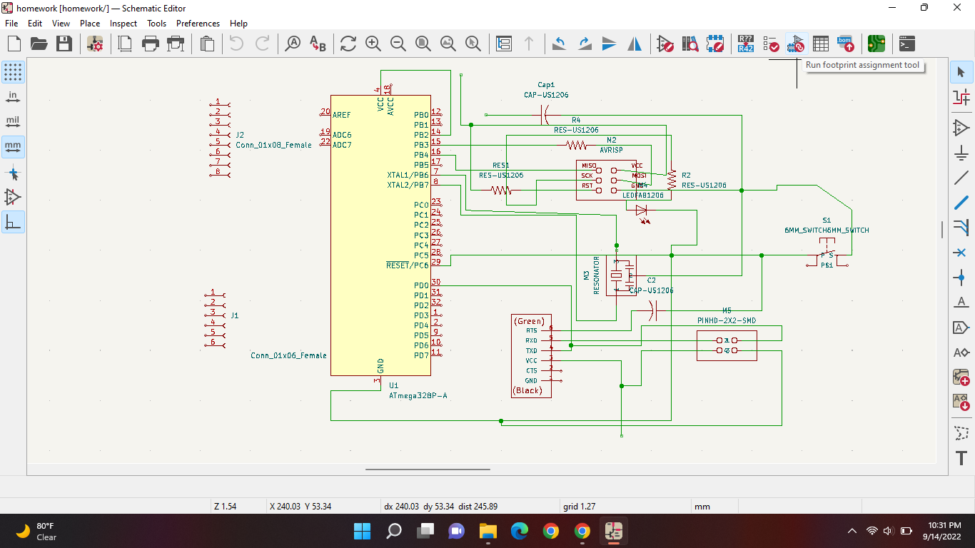
Homework now is to add all your footprints and connect everything like it's in here:
Saturday 10th of September 2022
Objective
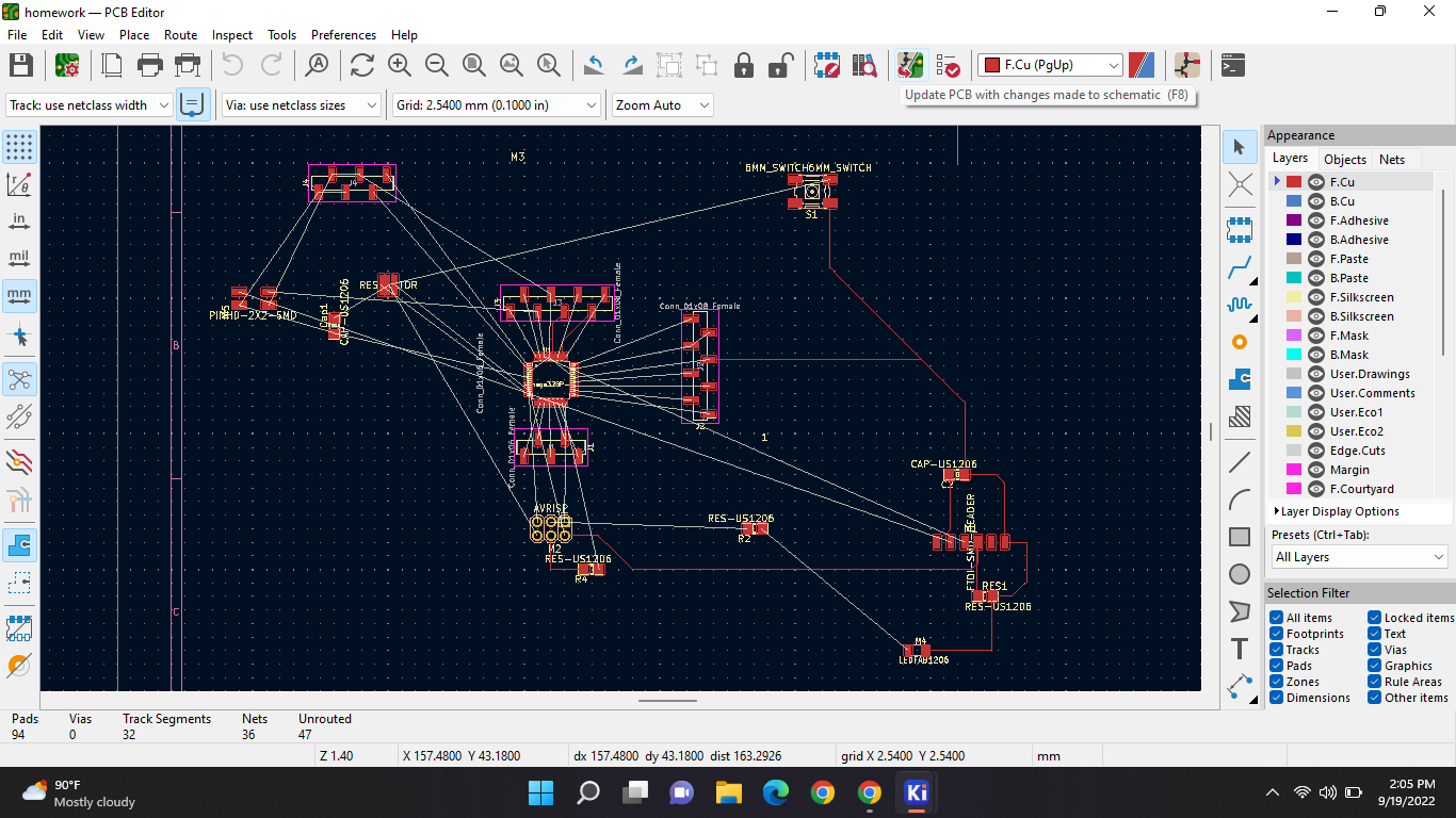
Today we had to add the paths from component to component with the help of kiCAD. This part in kiCAD is called PCB. We had to make this:
If you're done with that you go to the top and select the green icon
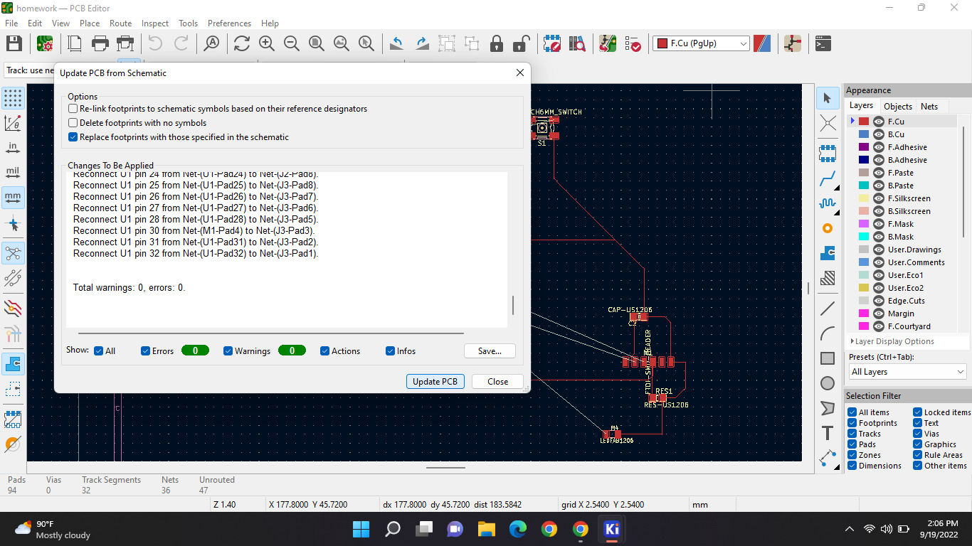
If youve selected that you should be let to another window. And should also see work but in darkmode. Then you select this icon that can be found above:
Then you should get this; and press update PCB. and there should be no errors if every cable is connected correctly.
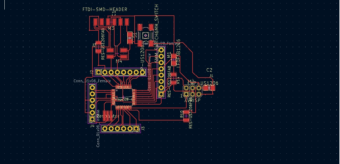
After that press close and you should see components attached to your mouse. Put those and the workplane and start pulling the components apart like this:
Then you go to the side and select the blue wire:
And now you can put a wire from one component to the other.
NOTE:
The wires cannot cross each other.
When you're done it should look like something like this:
Thursday 15th of September 2022
Objective
Documenting your research;
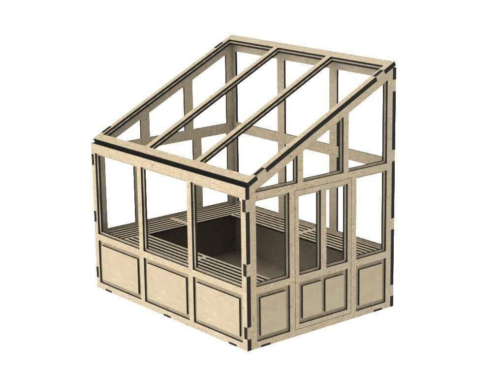
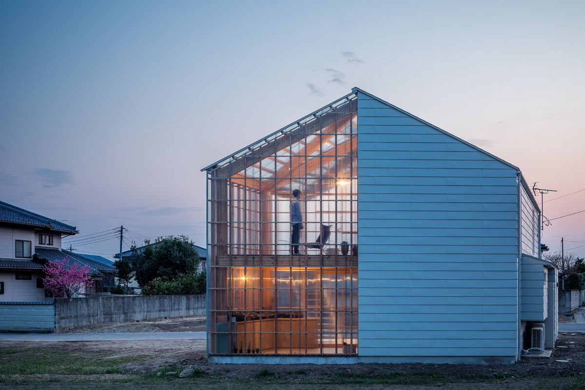
Another important thing is to always document what you've researched. And I did not do that. So today I'm gonna document my research and what I've come up with. So, I am gonna make an agriculture kit for kids. So they can have fun while planting stuff while also learning. And so it becomes their hobby and with that hobby they can also save the world. I was thinking of making a small greenhouse inside of another small house that is made to attract kids. So it doesn't look too boring. And with that little house I will teach how to blink a led. The green house will look like something like this:
And right next to this green house will be another small house. I have sketched the green house and all the dynamics.
the inside.
The house will be like the other half of the green house. So eventually it should look something like this:
I think i will start making a prototype with cardboard boxes.
This is also part of my research. This youtube video here. I have also researched a lot if an agriculture kit like mine (the one i want to make) already exists. But it doesn't. I researched a lot on amazon/ google and a lot more websites. But I haven't found one like this. I think it's because I will make a small one. That small one you can only let your plants grow a bit then you take it out and plant it in the ground. Now, what ill be using for this kit will be:
Some important articles that helped me:
Thursday 22th of September 2022
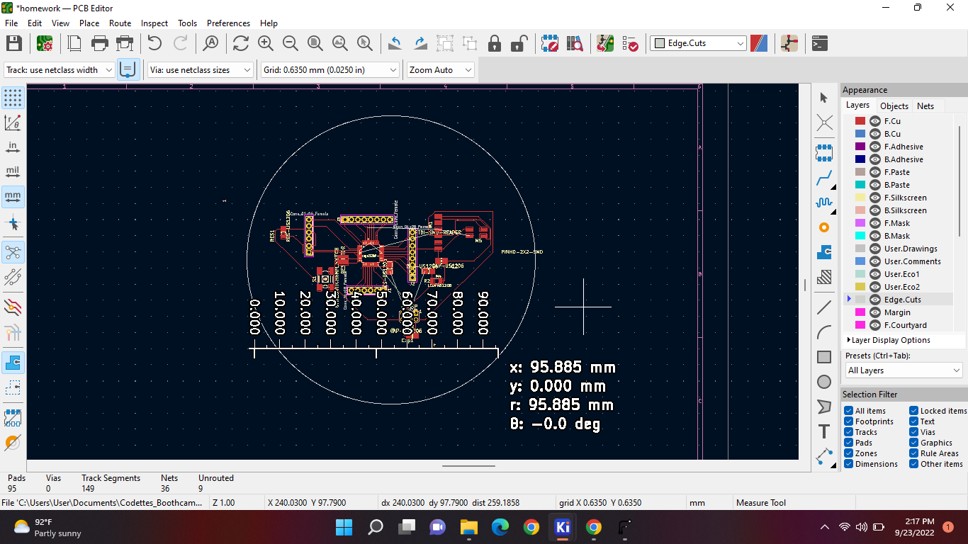
Objective
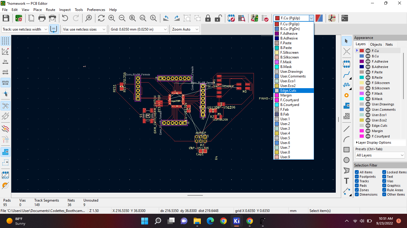
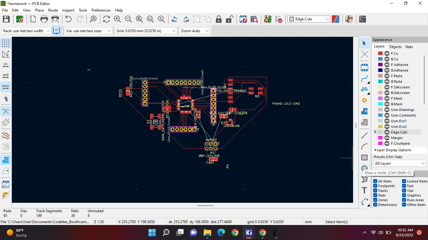
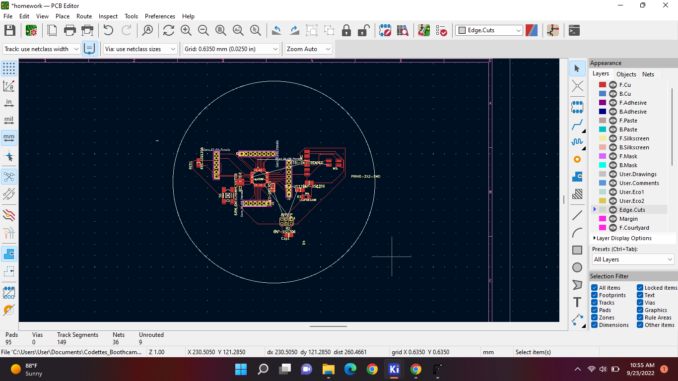
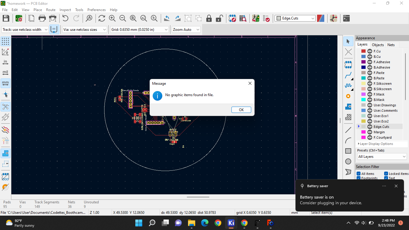
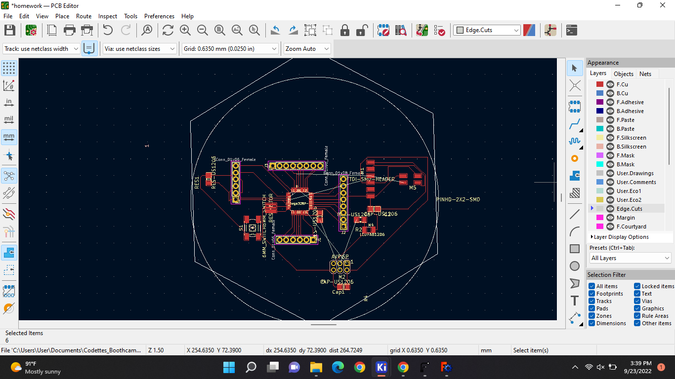
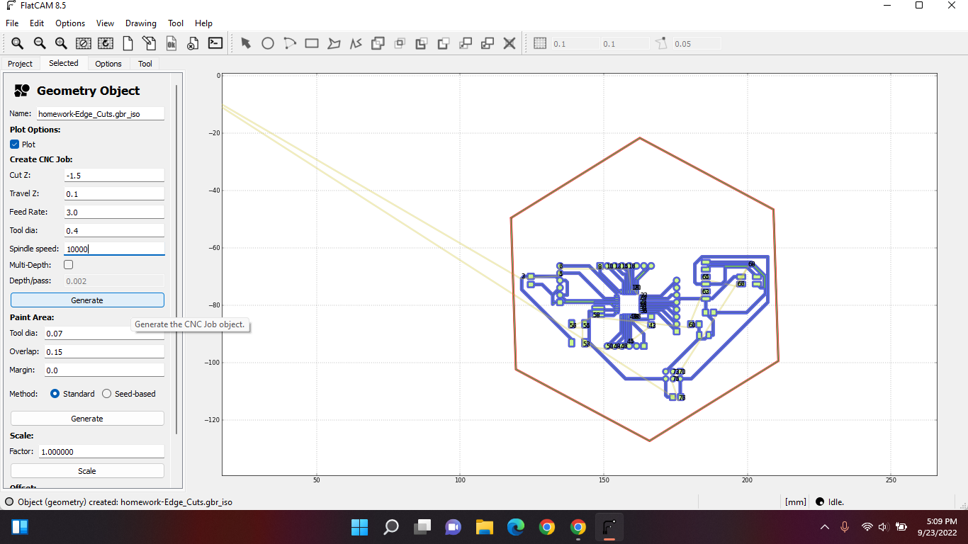
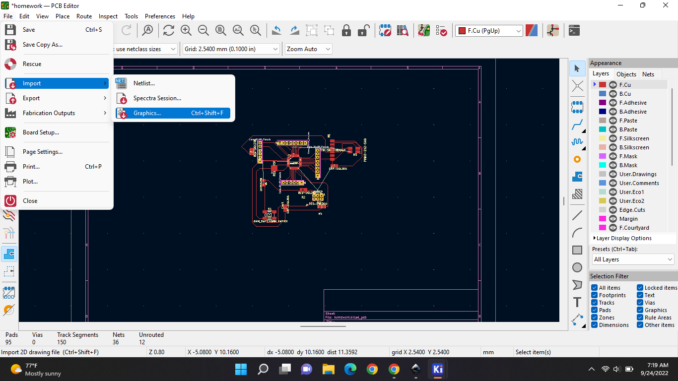
Today we did the edge cut of our “arduino”. So for that you have to have your pcb done. Everything should be wired. For the edge cut you have to have FlatCam installed. So first off go to your pcb design, you've been working on. Now switch to edge cut mode. Here on the top:
And now your gonna draw your own graphic lines with these options on the side bottom; you can either do a circle or a rectangle:
Like this:
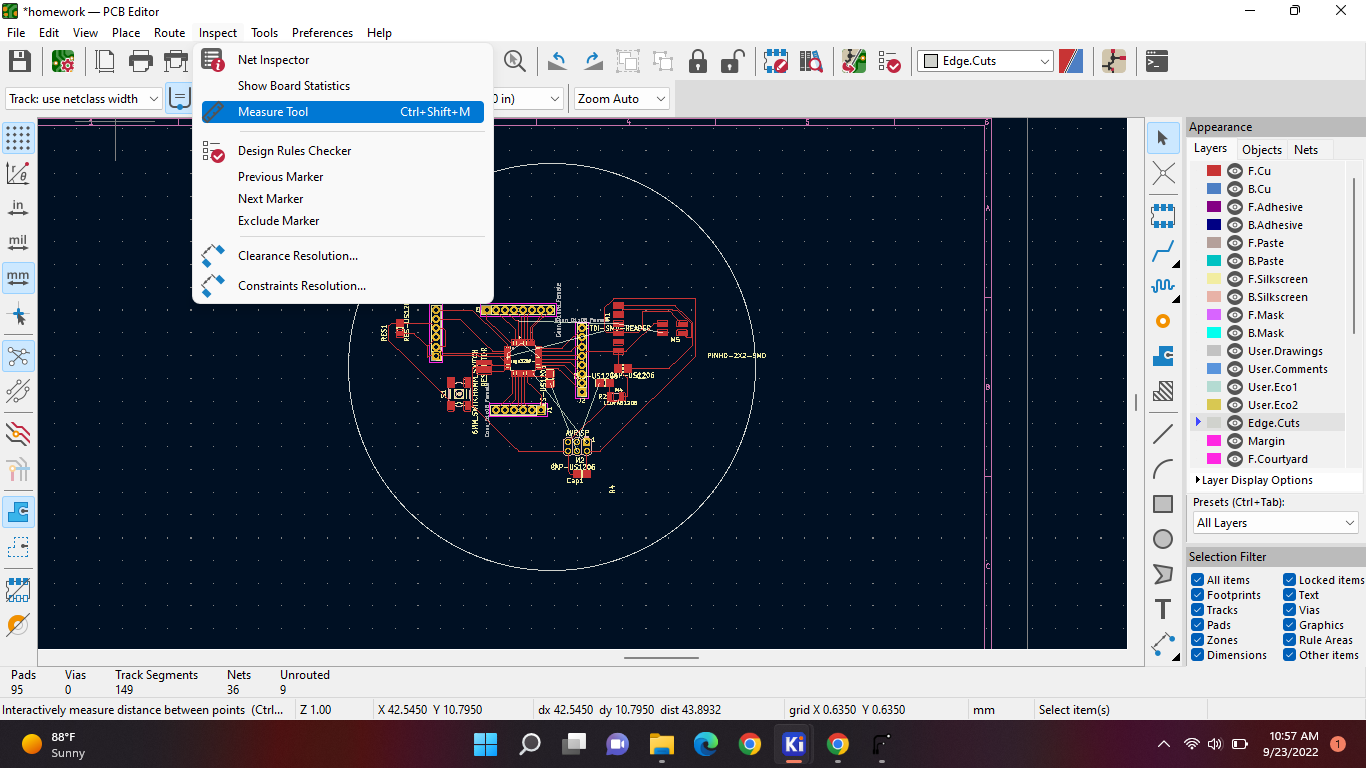
And now we're gonna measure our edges. And use freeCAD to design how our board can look. With this tool you can find on the top:
And then we're gonna place it next to our components. Like this:
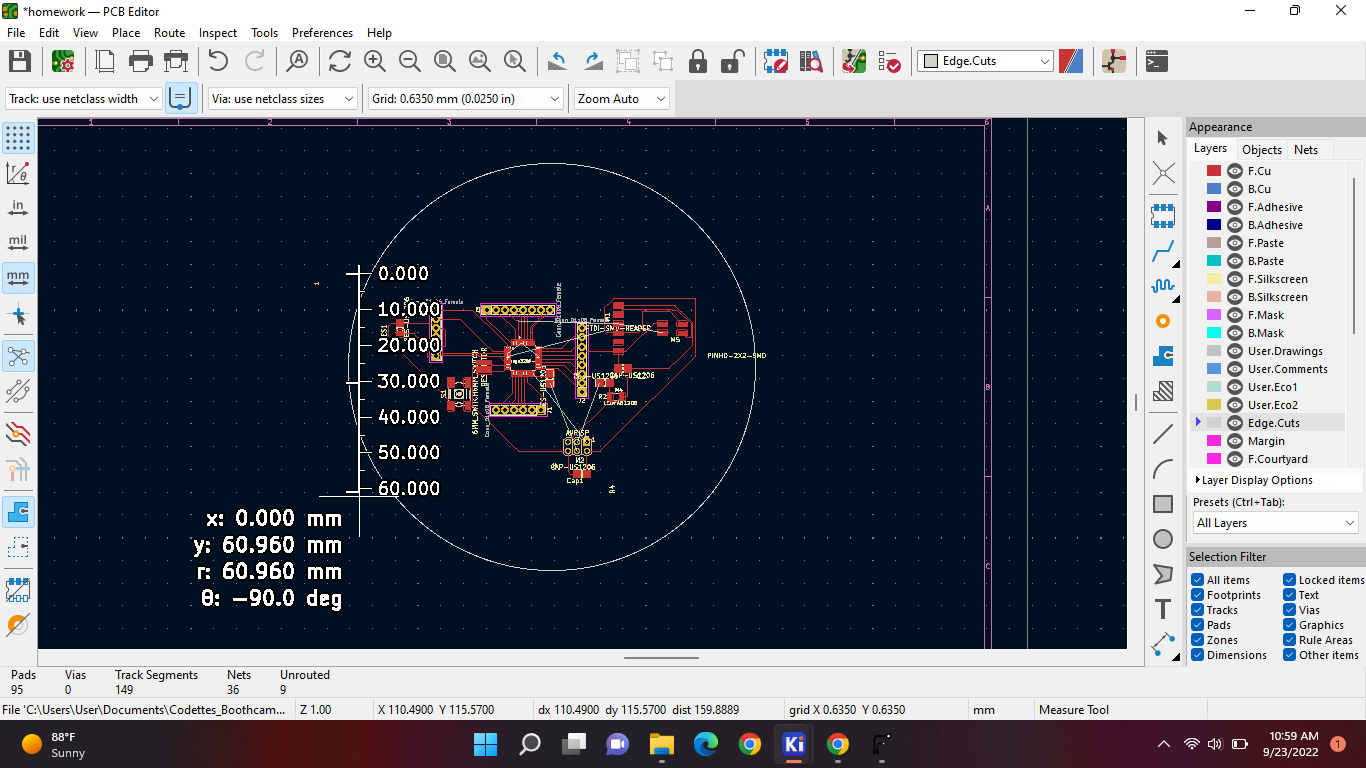
And as you can see, the height is y: 60.960 mm. And now im gonna measure the length the same way:
And the length is: 95.885.
The layout with the measurements;
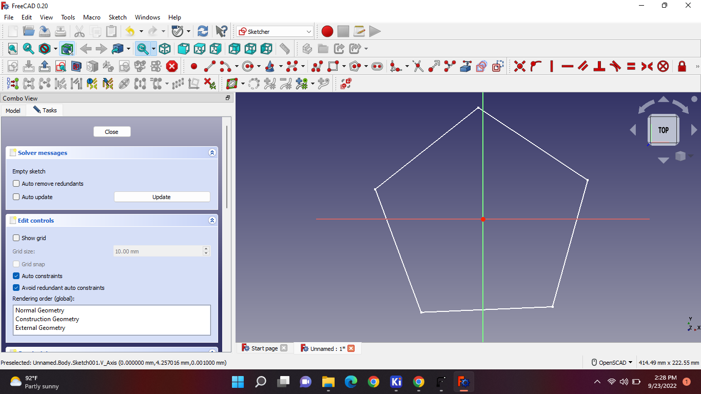
Step 1: open freeCAD, new file and go into part design mode.
Make a new sketch. And make a form you would like, and i like this:
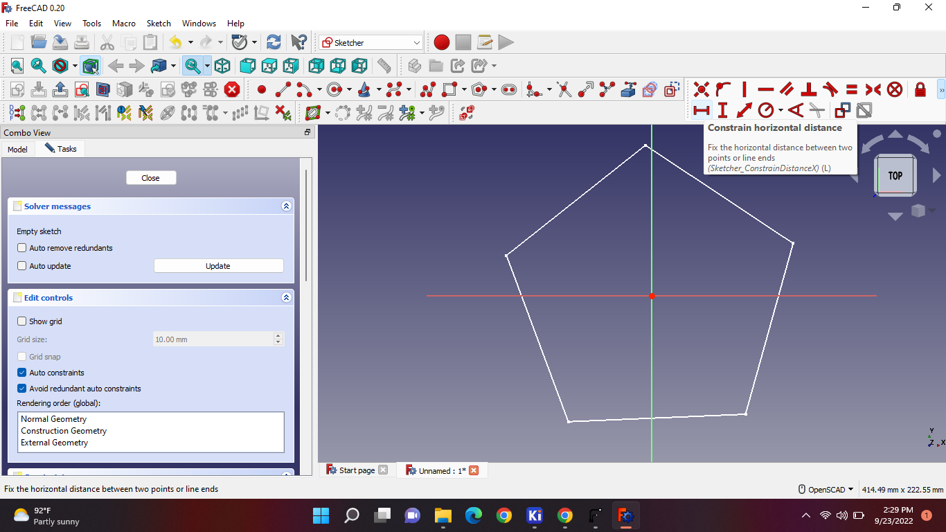
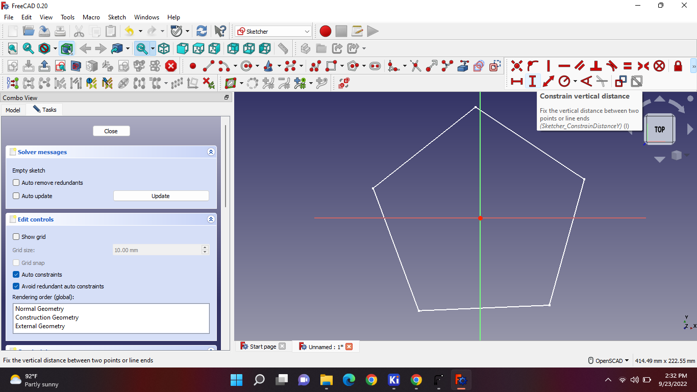
And i adjusted the measurements like this:
So you just take that and press the middle point and then to the left or the right. And put the mm you got in there. Remember this is horizontal and horizontal is “y”. When youve don that you go the other option that's next to the horizontal one:
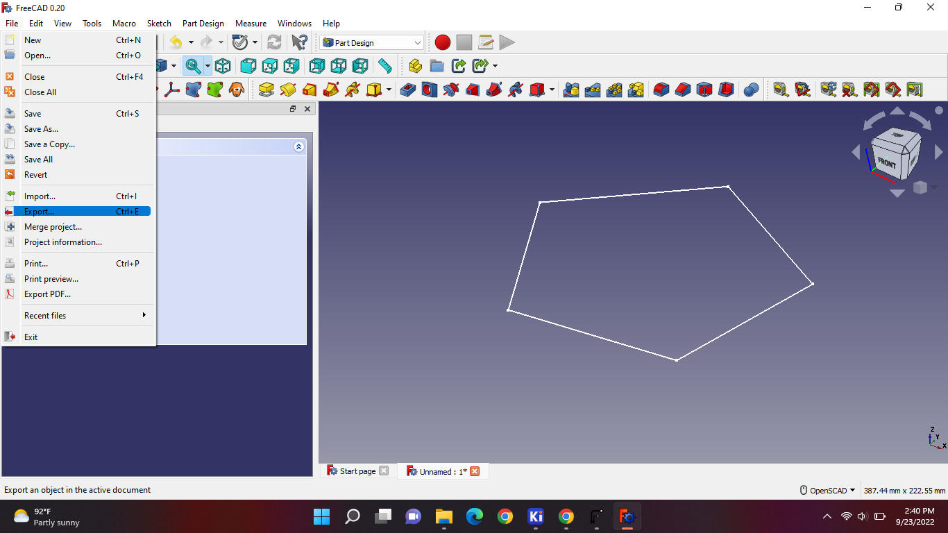
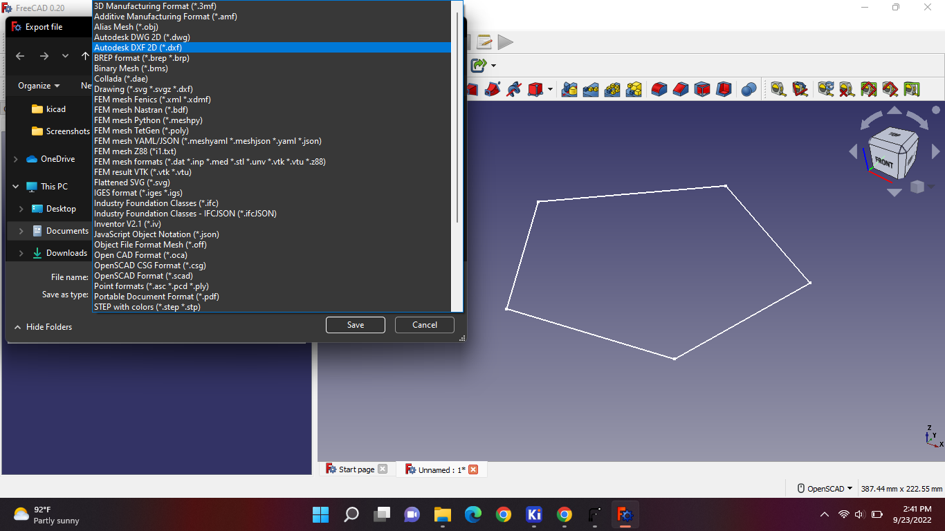
After you're done with you measure things. You can go ahead and export the file. And the file type should be “autodesk DXF”.
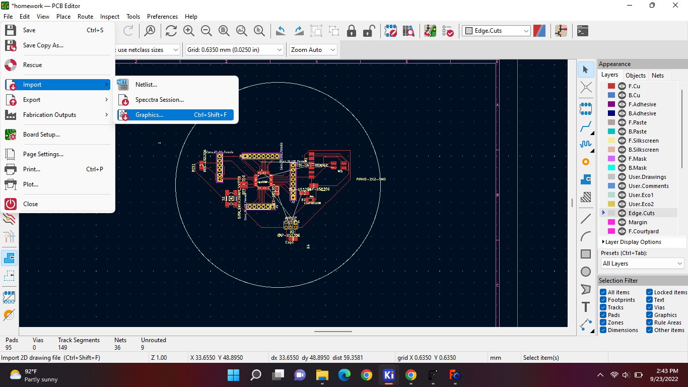
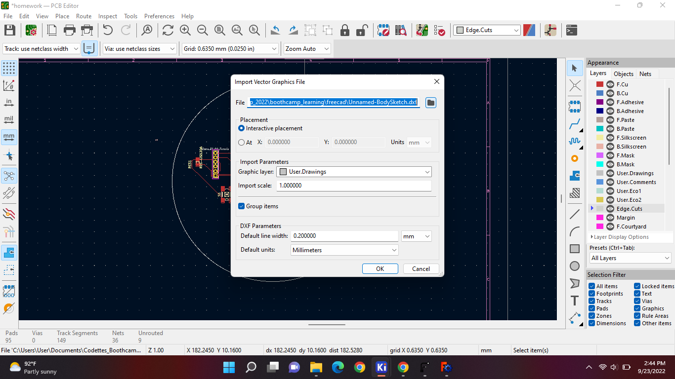
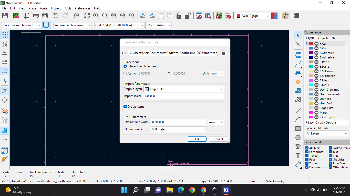
And now we go back to kiCAD and import the file in there as graphics:
Now go find your file where you saved it:
And here is the solution if you get this:
Now place your layout
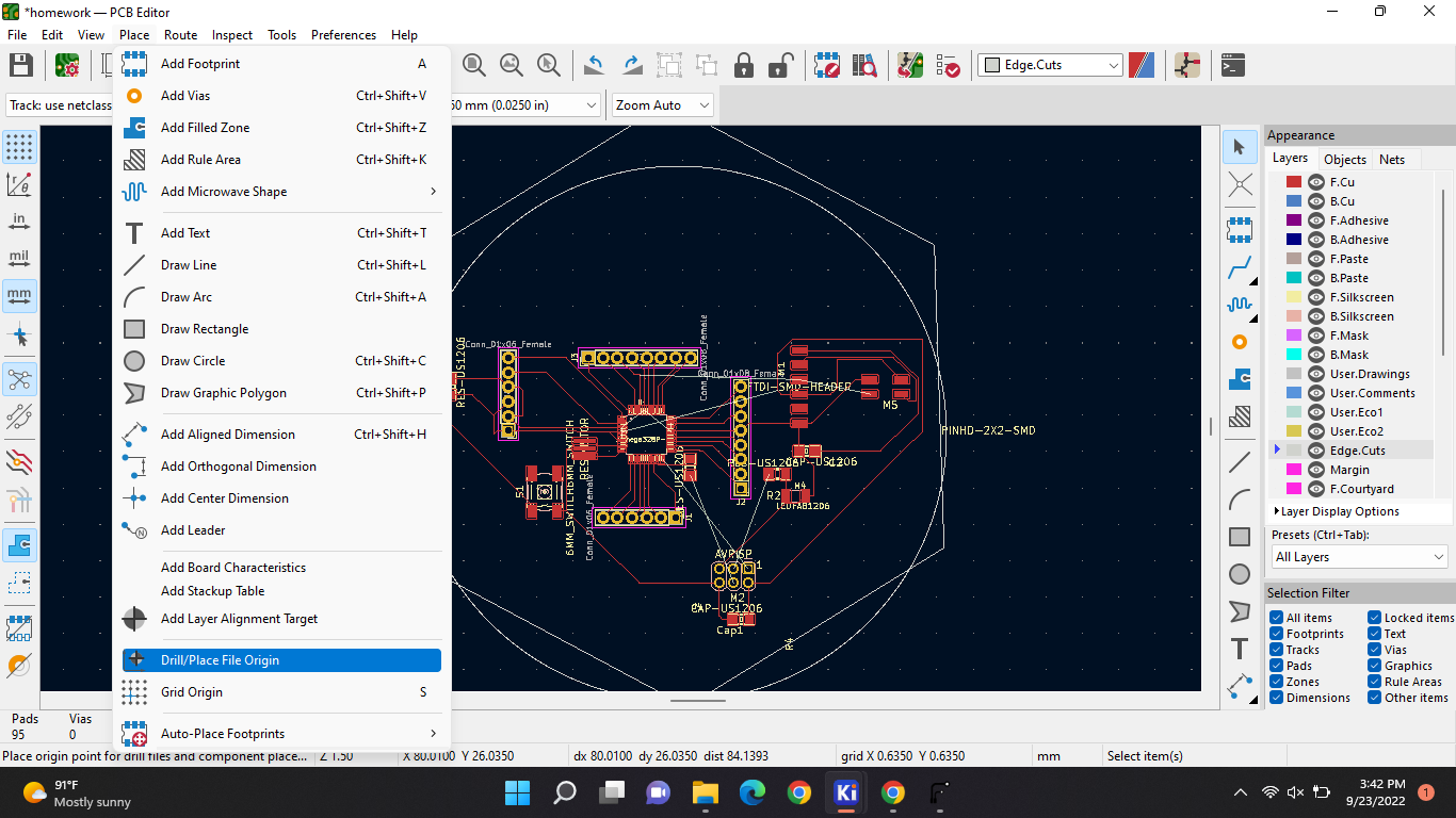
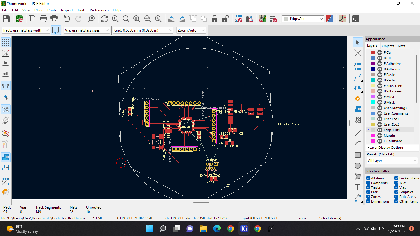
And now were gonna add our origin. With this:
And place it in the corner on the line:
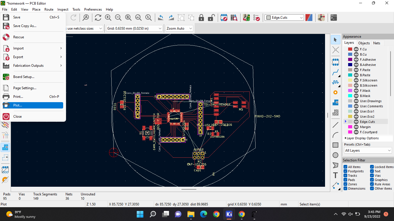
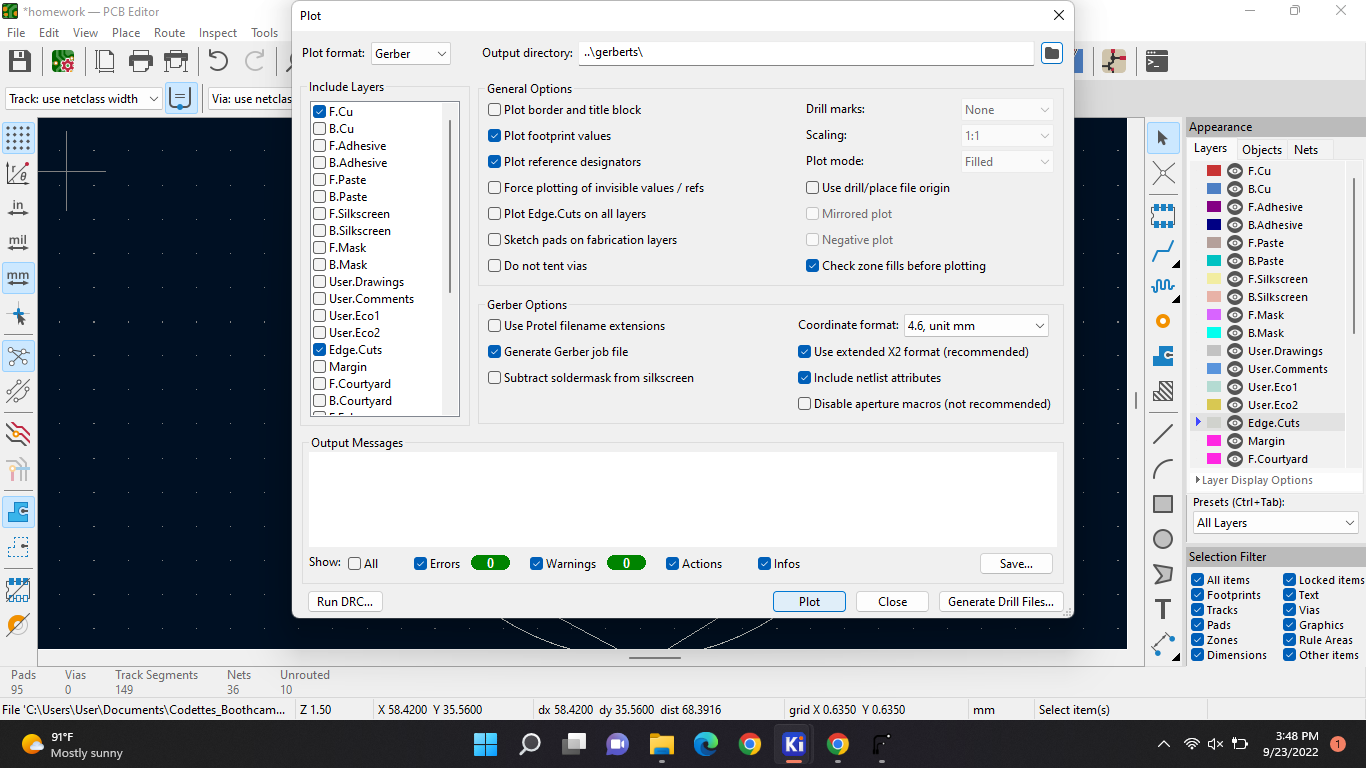
Now we will be plotting:
When you've selected that make sure everything is the same as it is in here:
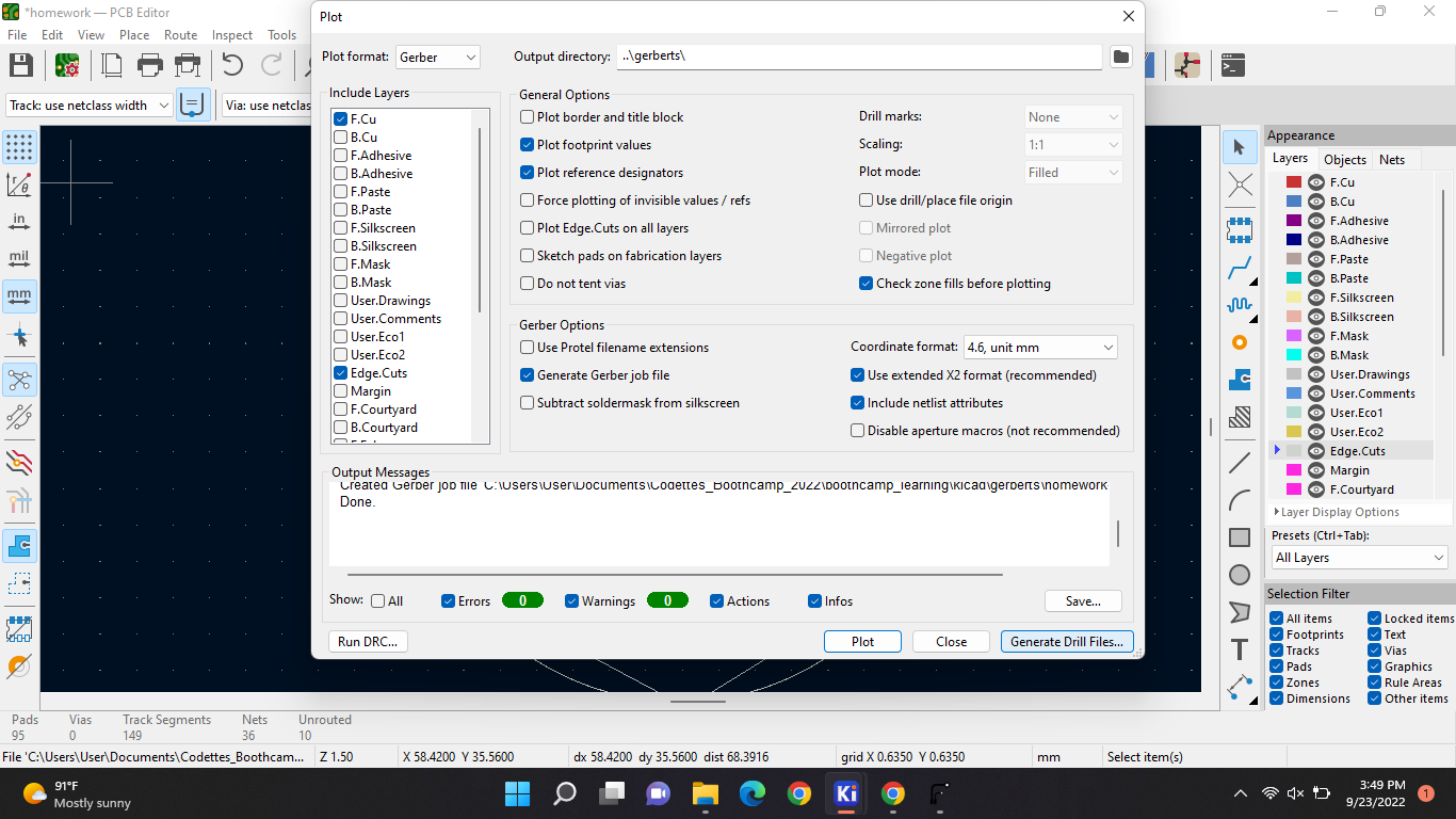
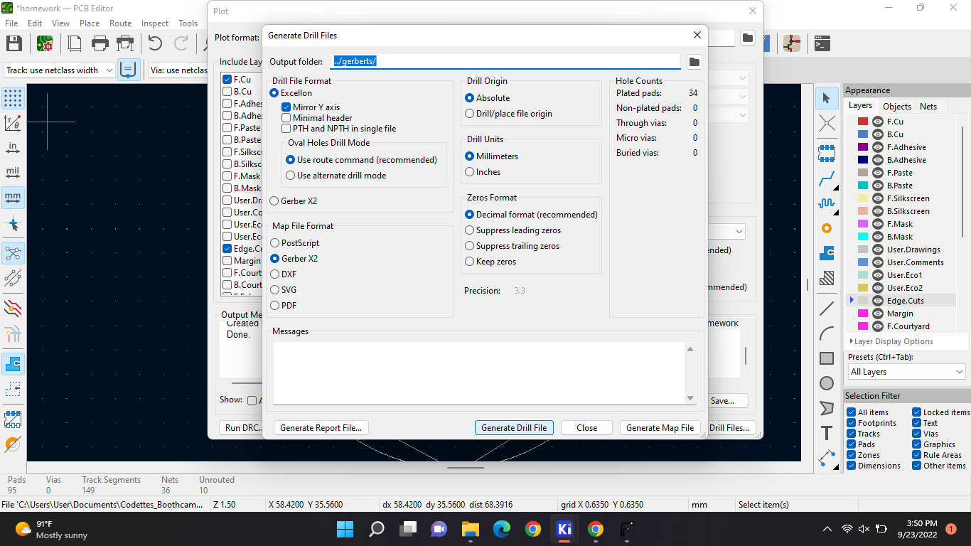
When you're done select “Plot”. And the “generate drill file”:
And then everything should be the same as it is in here again:
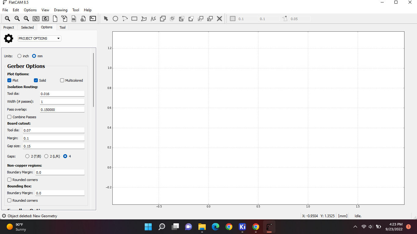
After that you close and open FlatCam on, then go to options and put it on mm:
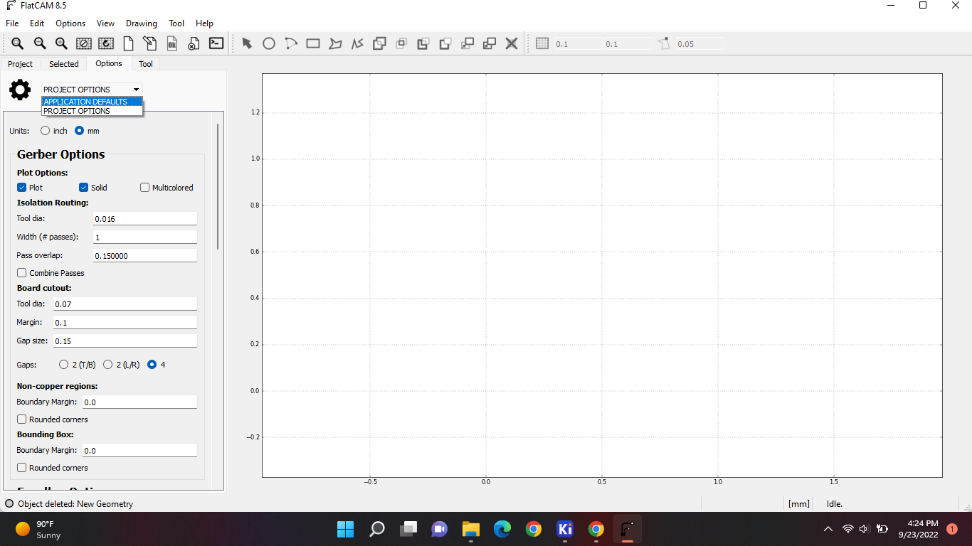
After that you wanna go to the drop down and put that also on mm.
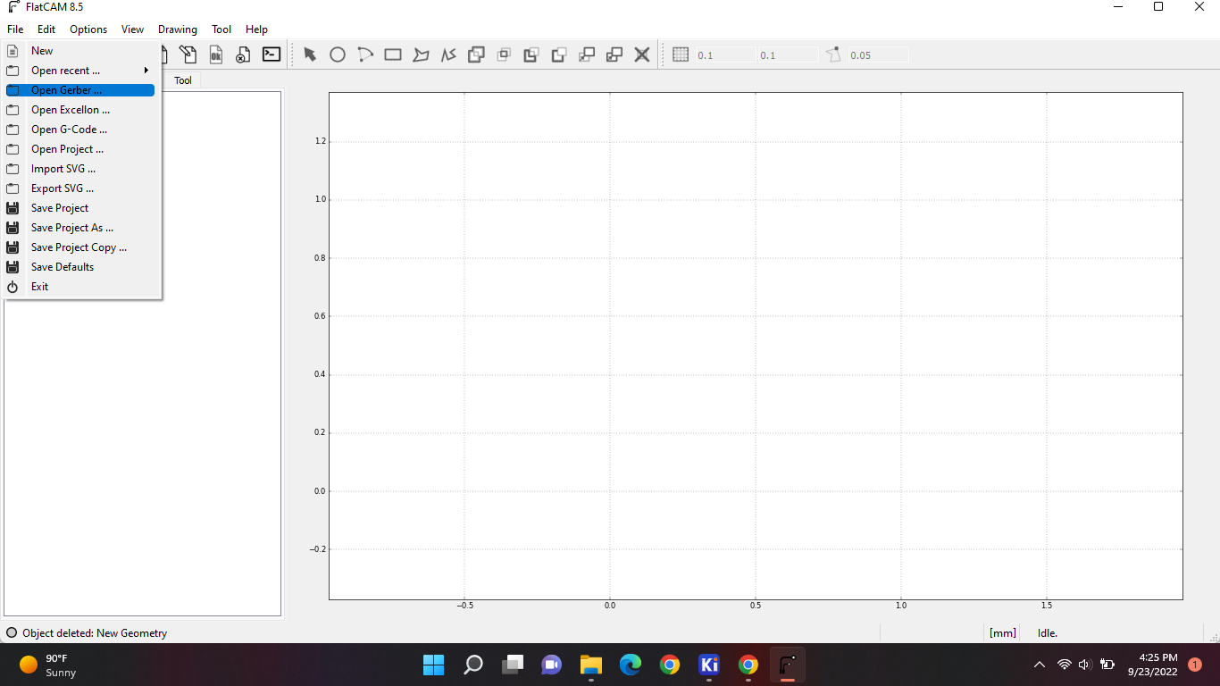
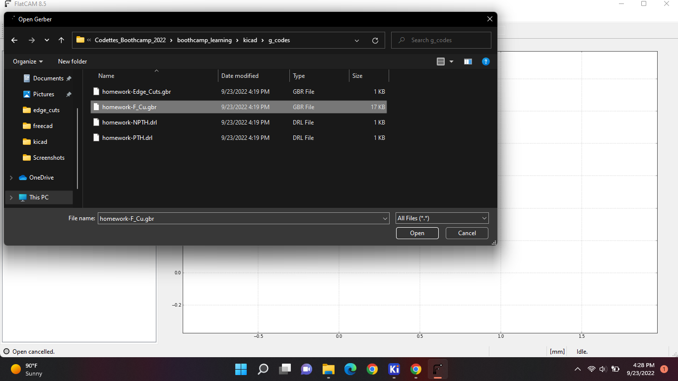
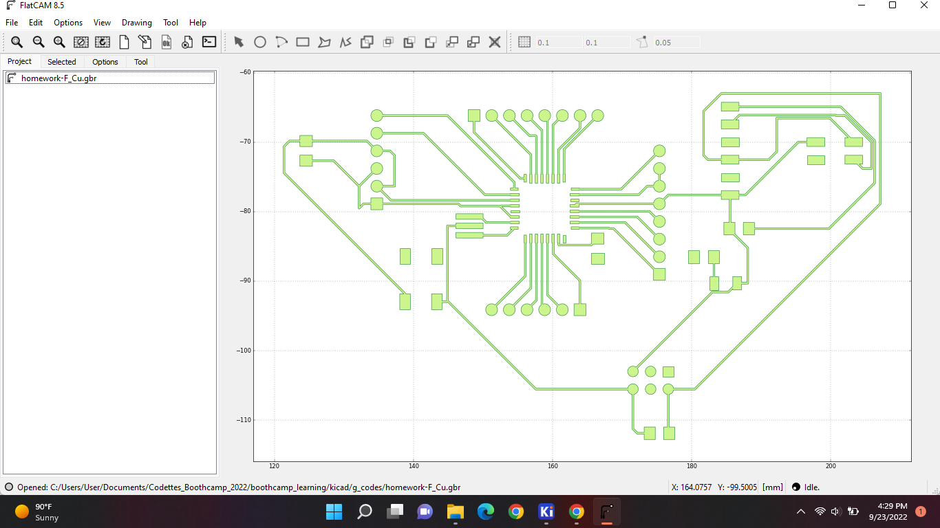
After that you wanna go back to projects > file > open Gerber. And select the file you just saved from KiCAD.
Then you wanna select this file out of the 4 files:
And you should see your components on your FlatCAM workplane:
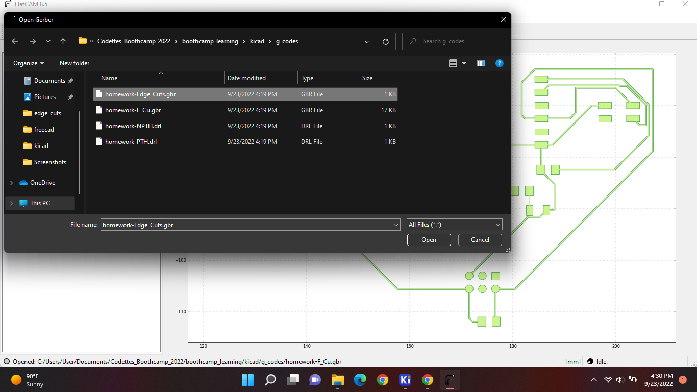
After that you wanna upload the other file:
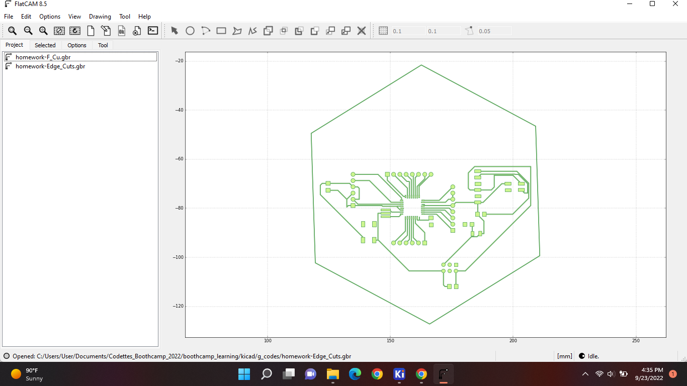
Now your project should look like this:
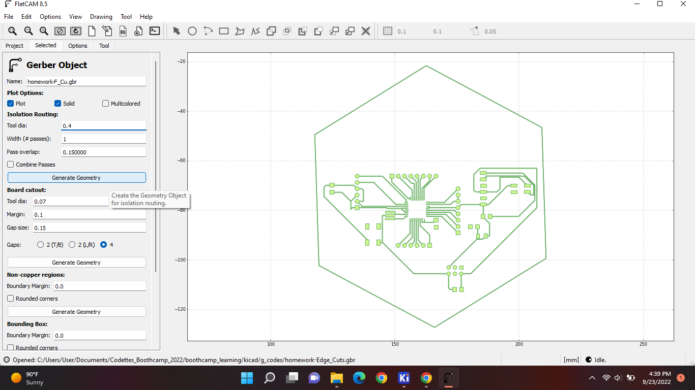
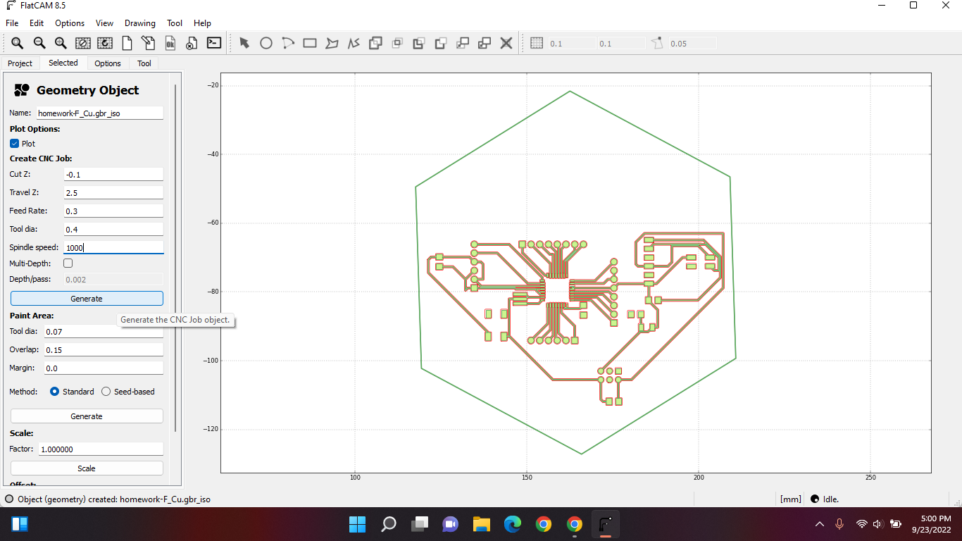
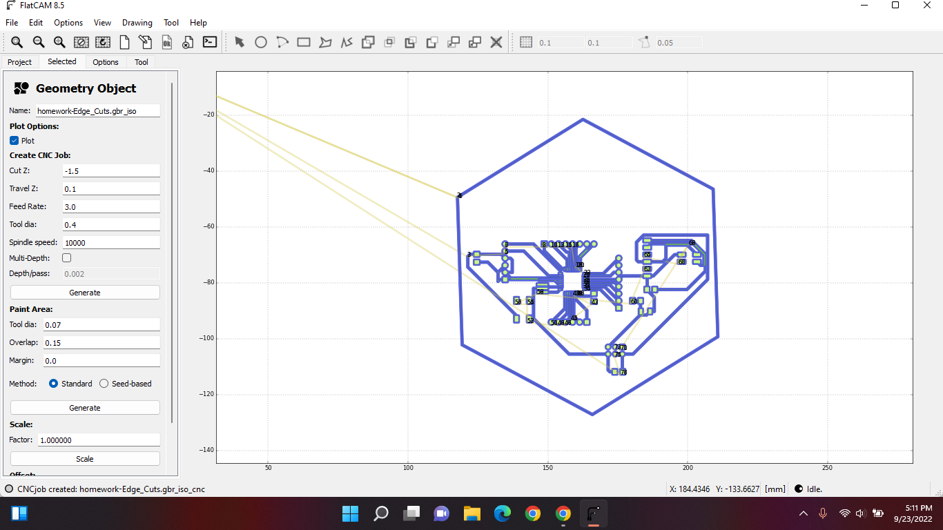
Now we're gonna add the machine parameters. Double click the “F_Cu.gbr” file. You should get some options. And for the machine we are using these are the right parameters. After that select generate geometry:
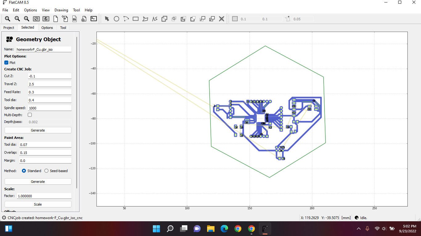
Now when you've generated it, go back to project and you should see a new file appears double click that and put these parameters in there; and the components should become blue.
]
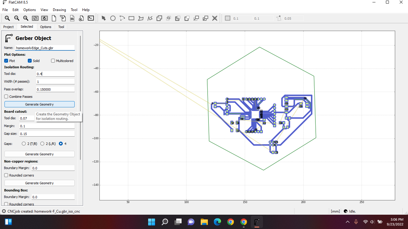
And for the edge cut parameters you add the same parameters and the edge should become red:
Then we go the new edge cut files and fill the same parameters in:
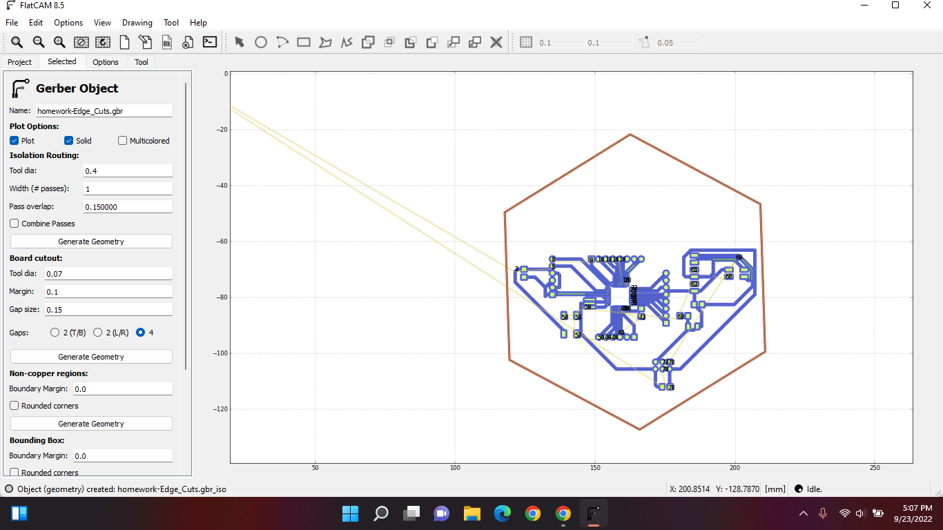
And everything should become blue.
Mistakes
NEVER leave an installation file in downloads.
Every machine is different. These parameters are not the same for every machine.
Today's class steps can also be found in these slides on pages 45-62.
Friday 23th of September 2022
Objective
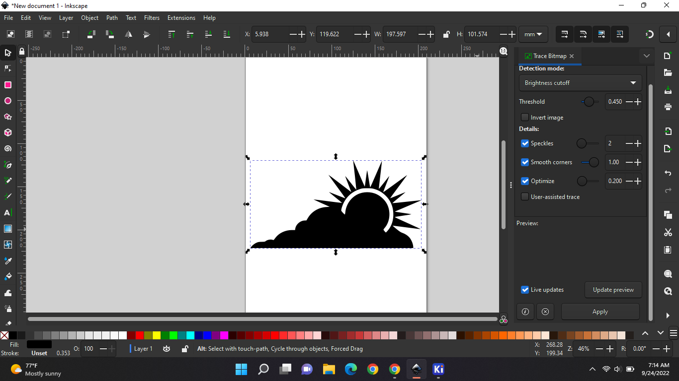
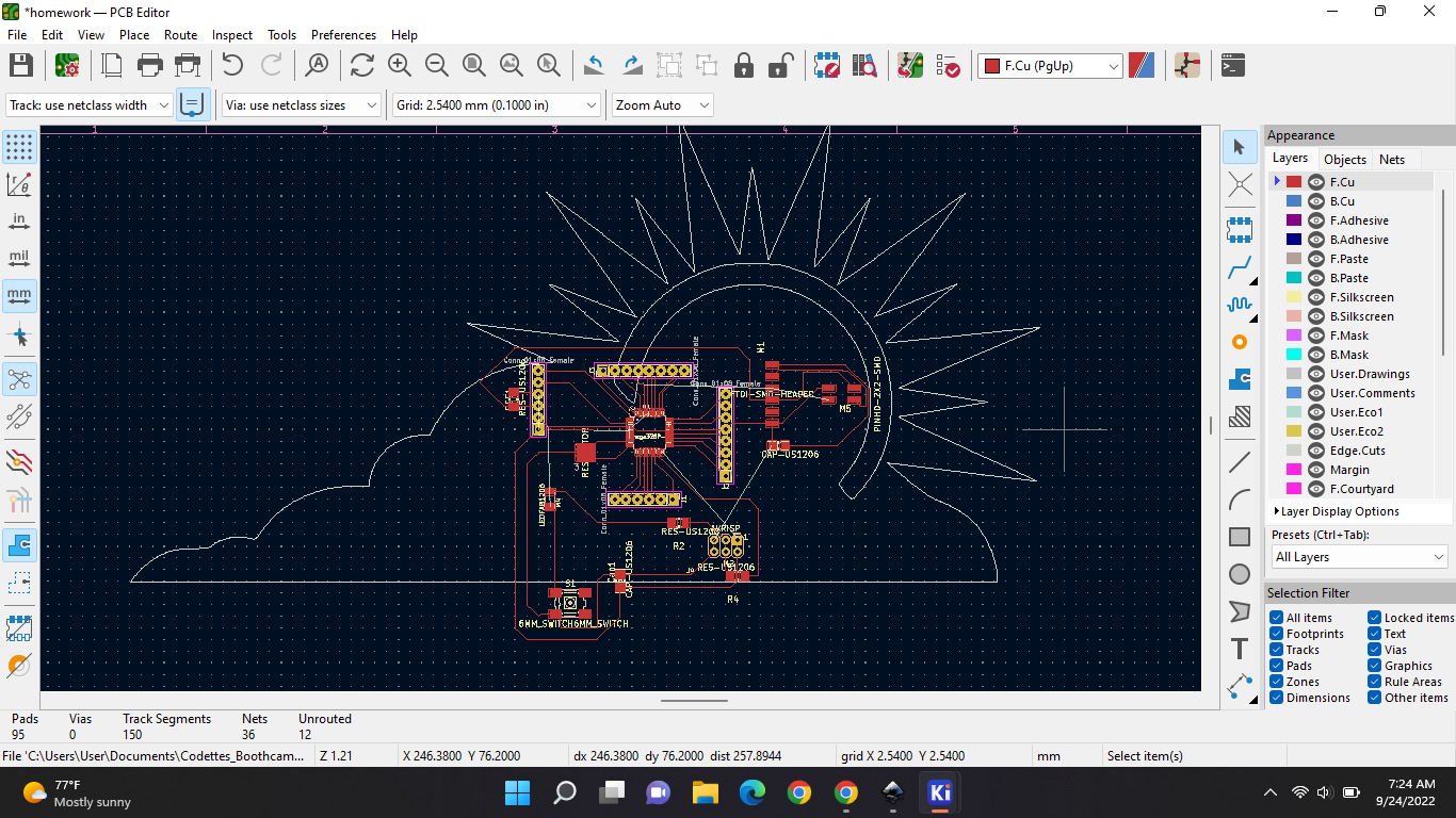
So in today’s class, we imported an image as an edge cut. And how big our board can go is till 9.5-6.5cm. First step, google a silhouette picture you like. Open inkscape and import.
Now go to Path > trace bitmap. Then you should get the side options, select update preview then apply. Then delete the pic and keep the bitmap:
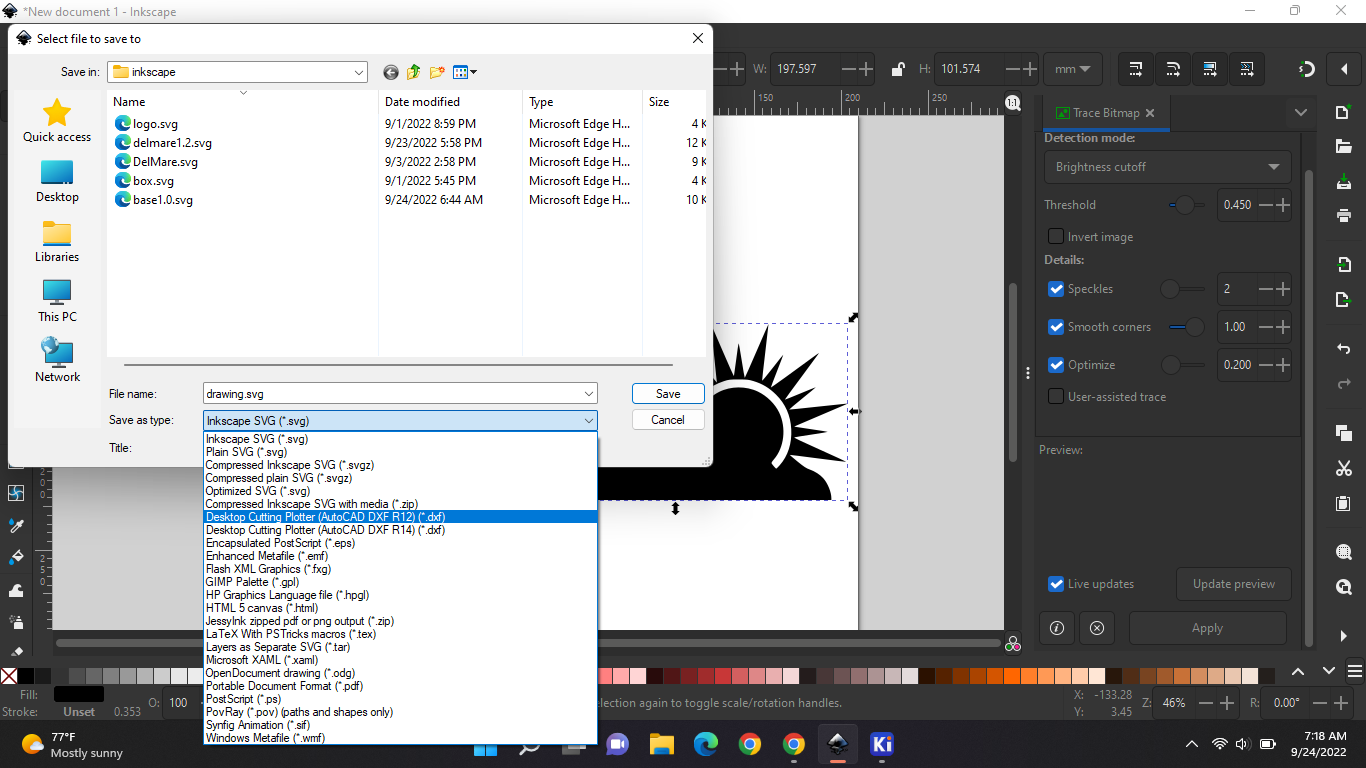
Save file as a desktop cutting plotter(dxf*)
Now open your kiCAD pcb. Go to file > import > graphics; and import your inkscape picture
Before importing don't forget your layer should be on edge cuts and everything else should be on mm:
As you can see in the picture above, the edge cut is too big, so you have to adjust the measurements in InkScape. Also my components are far from each other. And homework is to make my cables even thicker.
Saturday 24th of September 2022
Objective
Today Mr. Theo showed us, with what we would be milling our boards.
Thursday 6th of October 2022
Objective
Today mr. Theo showed us how our documentation should look like for this whole bootcamp. And how especially our final project documentation should look like. There should be sketches at, that's always so, because everything starts on a piece of paper. Maybe talk a bit about your inspiration. How your user experience is. This is an example.
Thursday 20th of October 2022
Objective
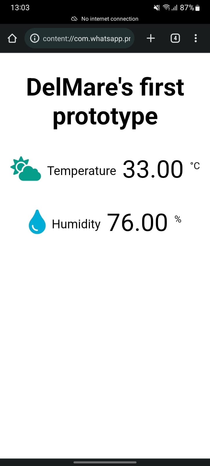
This is how I will be making the temperature sensor work with a website.
This is what I got so far.
The final project
DelMare_Jia This is my final presentation that I will be presenting to the sponsors.
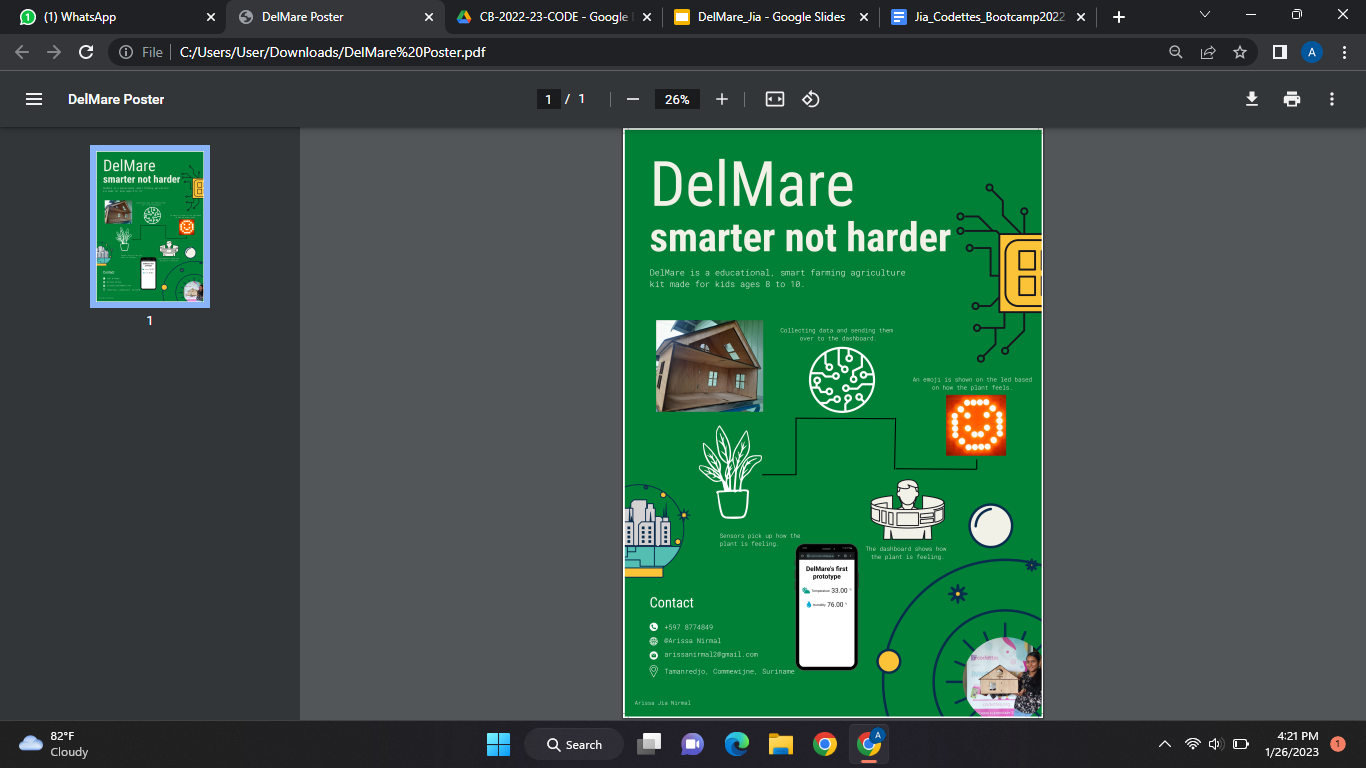
My poster;
My first target audience with this project will be my childhood school, OS2 Tamanredjo.